X7+ Pro Wiring Quick Start
This quick start guide shows how to power the X7+ Pro flight controller and connect its most important peripherals.
NOTE This chapter applies to X7 and X7+ Pro flight controllers.
Wiring Chart Overview
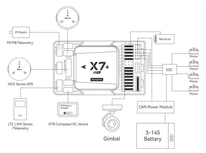
The image below shows how to connect the most important sensors and peripherals (except the motor and servo outputs). We'll go through each of these in detail in the following sections.
| Main interface | Function |
|---|---|
| POWER A | Connect power module. Power input with analog voltage and current detection. Do not use a Digital PM on this connector! |
| POWER C | Please connect CAN PMU SE to this interface; this interface is connected to UAVCAN power module |
| GPS&SAFETY | Connect Neo series GPS or C-RTK 9P, including GPS, safety switch, buzzer interface. |
| UART 4 | Can be used to connect to GPS, can be used as a second GPS |
| TELEM1/TELME2 | Connect to the Telemetry System |
| TF CARD | SD card for log storage (card pre-inserted in factory). |
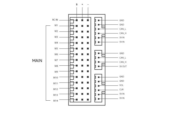
| M1~M14 | PWM signal output port, which can be used to control motors or steering gears; and M1~M12 also support dshot protocol |
| DSU7 | Used for FMU chip debugging, read DEBUG device information |
| TYPE-C(USB) | Connect to a computer for communication between the flight controller and the computer, such as loading firmware. |
| I2C1/I2C2/i2C4 | Connect an I2C device such as an external compass. |
| CAN1/CAN2 | Connect UAVCAN devices such as CAN GPS. |
| RC IN | Including DSM, SBUS, RSSI signal input interface, DSM interface can be connected to DSM satellite receiver, SBUS interface to connect SBUS remote control receiver |
| RSSI | RSSI for signal strength return module |
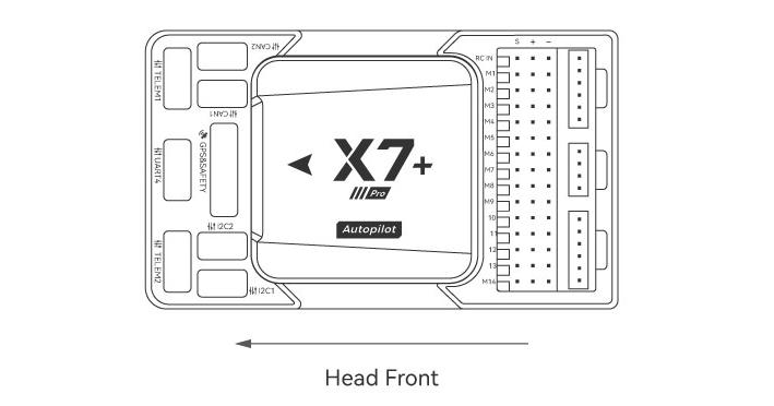
Vehicle Front
NOET If the controller cannot be mounted in the recommended/default orientation (e.g. due to space constraints) you will need to configure the autopilot software with the orientation that you actually used: Flight Controller Orientation.(for PX4 firmware, for Ardupilot firmware).
GPS
We recommend that you use UAVCAN GPS/RTK (such as Neo 3 pro); you only need to connect it to the CAN 1/2 interface; you can also use an ordinary GPS/RTK module; connect it to the GPS interface; it is commonly used now The GPS module generally integrates GPS, compass, safety switch, buzzer, and LED status light. The GPS module should be installed on the bracket and far away from other electronic devices. The installation direction is towards the front of the carrier (the NEO GPS arrow is in the same direction as the flight control arrow)
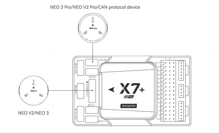
NOTE X7+ Pro may not be fully compatible with ordinary GPS modules of other manufacturers. If you need to use ordinary GPS, please choose NEO V2; for a better experience, we recommend you to use UAVCAN GPS.
safety switches
NOTE When you use NEO series GPS, there is no need to install additional safety switches.
If you are flying without GPS, you must connect the switch directly to the GPS1 port to be able to Arm and fly the drone. (If you use the old 6-pin GPS, please check the interface definition at the bottom to change the line).
Buzzer
NOTE When you use NEO series GPS, there is no need to install additional Buzzer.
If you use other manufacturers' gps, the buzzer may not work.
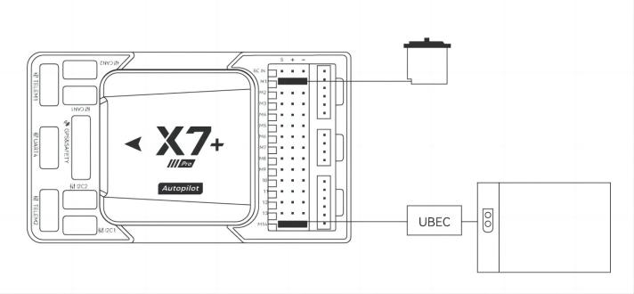
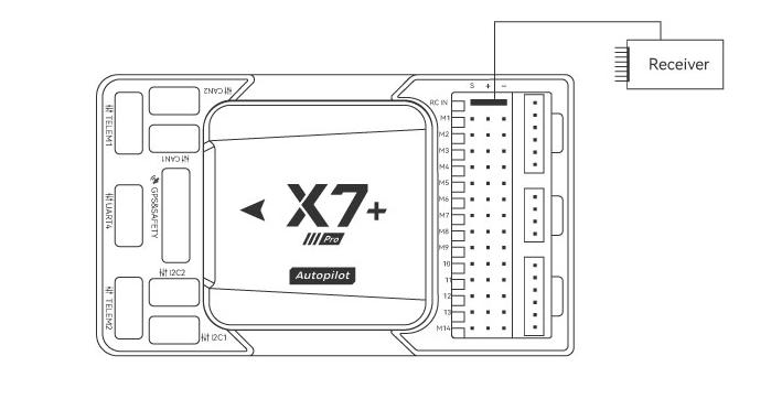
Radio Control
For your flight safety, it is recommended that whether you fly manually or automatically, please connect the handheld remote control (it can be used as an emergency machine, unless you are not proficient in operating the handheld remote control).
The figure below shows how you can connect to your remote control receiver (please find the Dupont cable in the package)
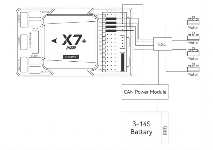
Power
X7+ Pro is equipped with CAN PMU Lite module, it supports 3~14s lithium battery, please connect the 6pin connector of the module to the flight control Power C interface
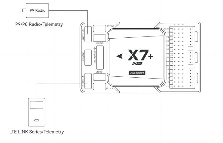
Telemetry (Radio) system
Using the telemetry system you can communicate with the drone through the ground station software. Monitor and control drones in flight. The airborne end of the telemetry system should be connected to the TELEM1/TELEM2 interface.
SD Card
The SD card is already installed on X7+ Pro when it leaves the factory, so you don't need to install it.
Motors/Servo
The motor/servo system is connected to the M1~M14 ports in the order specified for your carrier in the fuselage reference.
Servo power supply
The servo interface of X7+ Pro is completely isolated from the internal power supply of the flight controller. The flight controller will not supply power to the steering gear. If you need to supply power to the steering gear, please connect the BEC to any of the positive and negative stages of M1~M14 (M1~M14) The positive and negative times of the two are connected); then connect the Servo.