P8 Configuration
Configuration Guide
[!Tip] The P8 is fully configured at the factory and supports plug-and-play for most use cases. If you have specific requirements, follow the instructions below for configuration.
Driver Installation
If your computer prompts for a missing driver after USB connection (as shown in the image below):
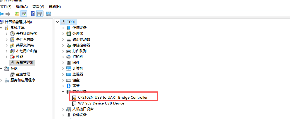
Download the driver software (CP2102), extract the files, and install it.
[!NOTE]
- For Windows 64-bit systems: Install CP210xVCPInstaller_x64.exe
- For Windows 32-bit systems: Install CP210xVCPInstaller_x86.exe
- For macOS and other systems: Search for "CP2102 driver" in your preferred search engine.
Enter Configuration Mode
- Download and install a serial port assistant tool or other serial communication software.
- Connect the data transmission module to your computer via USB and launch the serial port assistant.
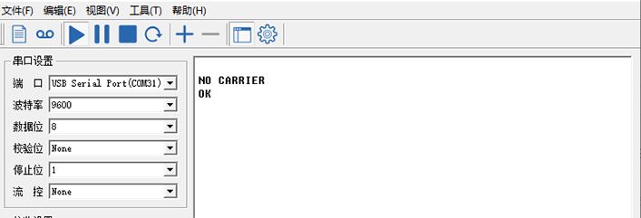
Method 1:
- Select the USB COM port of the data transmission module, set the baud rate to 9600, data bits to 8, parity to none, stop bit to 1, and both transmission/reception to ASCII.
- Use tweezers or a similar tool to press and hold both the CONFIG and RESET buttons. Release the RESET button first, then release the CONFIG button.
Method 2:
- Select the USB COM port of the data transmission module, set the baud rate to the module's current baud rate (factory default: 57600), data bits to 8, parity to none, stop bit to 1, and both transmission/reception to ASCII.
Send the following command:
+++[!NOTE]
- Method 2 is recommended with the SSCOM serial assistant (some serial tools may fail to send this command).
- Do NOT press Enter/Return to line break after this command.
The serial assistant will display "NO CARRIER ok" to confirm successful entry into AT configuration mode.
Enter the parameters in the serial assistant and click "Send" to complete configuration (each successful configuration will return "ok").
[!NOTE] Press Enter/Return to line break after each AT command (including the last one).
Common Parameter Explanations:
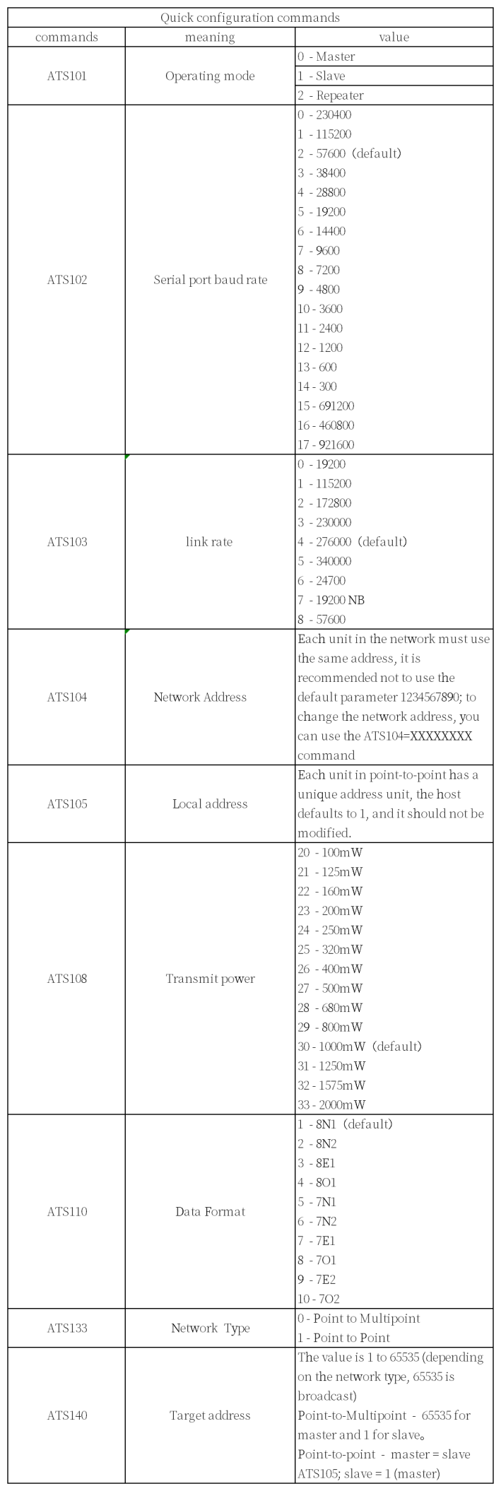
[!NOTE] Use the
AT&Vcommand to query the current configuration.
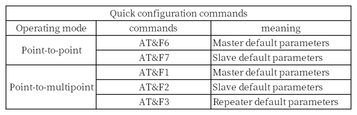
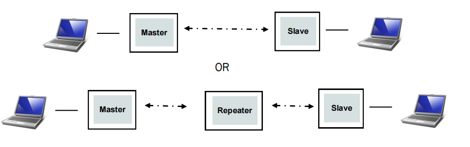
Point-to-Point (P2P) Communication Configuration
For P2P mode, copy the parameters below into the serial assistant, press Enter/Return, and click "Send" to complete configuration (each successful configuration will return "ok").
Master Station Configuration (Ground)
Parameter Restrictions:
- ATS105 range: 1
- ATS140 range: 2 ~ 65535
Parameter Description: Set to master mode, baud rate 57600, air data rate 276000, network IP 725527, transmit power 1000MW, device address 1, target address 2.
AT&F6
ATS102=2
ATS103=4
ATS104=725527
ATS108=30
ATS105=1
ATS140=2
AT&W
Slave Station Configuration (Air)
Parameter Restrictions:
- ATS105 range: 2 ~ 65535
- ATS140 range: 1
Parameter Description: Set to slave mode, baud rate 57600, air data rate 276000, network IP 725527, transmit power 1000MW, device address 2, target address 1.
AT&F7
ATS102=2
ATS103=4
ATS104=725527
ATS108=30
ATS105=2
ATS140=1
AT&W
P2P Configuration with Repeater
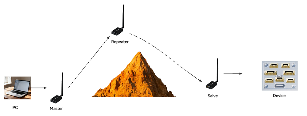
Master Station Configuration (Ground End)
Parameter Restrictions:
- ATS105 range: 1
- ATS140 range: 2 ~ 65535
Parameter Description: Set to master mode, baud rate 57600, data rate 276000, network IP 725527, transmit power 1000MW, device address 1, target address 2.
AT&F6
ATS102=2
ATS103=4
ATS104=725527
ATS108=30
ATS105=1
ATS140=2
ATS141=1
AT&W
Slave Station Configuration (Ground End)
Parameter Restrictions:
- ATS105 range: 1
- ATS140 range: 2 ~ 65535
Parameter Description: Set to master mode, baud rate 57600, data rate 276000, network IP 725527, transmit power 1000MW, device address 2.
AT&F7
ATS102=2
ATS103=4
ATS104=725527
ATS108=30
ATS105=2
ATS118=3
ATS140=1
AT&W
Repeater Configuration (Air End)
Parameter Restrictions:
- ATS105 range: 2 ~ 65535
- ATS140 range: 1
Parameter Description: Set to slave mode, baud rate 57600, data rate 276000, network IP 725527, transmit power 1000MW, device address 2.
AT&F7
ATS101=1 (Repeater)
ATS102=2
ATS103=4
ATS104=725527
ATS108=30
ATS105=3
ATS118=1
ATS140=1
AT&W
Point-to-Multipoint (P2MP) Communication Configuration
For P2MP mode, copy the parameters below into the serial assistant, press Enter/Return, and click "Send" to complete configuration (each successful configuration will return "ok").
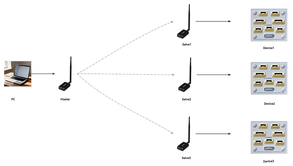
Master Station Configuration
- Parameter Restrictions:
- ATS105 range: 1
ATS140 range: 65535
Parameter Description:
- Set to master mode, baud rate 230400, data rate 340000bps, network IP 725527, transmit power 1000MW, device address 1, target address 65535.
AT&F1
ATS102=0
ATS103=5
ATS104=725527
ATS108=30
ATS105=1
ATS118=3
AT&W
Slave Station 1 Configuration
Parameter Restrictions:
- ATS105 range: 2 ~ 65535 (must be unique among slaves)
- ATS140 range: 1
Parameter Description: Set to slave mode, baud rate 230400, data rate 340000bps, network IP 725527, transmit power 1000MW, device address 2, target address 1.
AT&F2
ATS102=0
ATS103=5
ATS104=725527
ATS108=30
ATS105=2
ATS140=1
AT&W
Slave Station 2 Configuration
- Parameter Restrictions:
- ATS105 range: 2 ~ 65535 (must be unique among slaves)
ATS140 range: 1
Parameter Description:
- Set to slave mode, baud rate 230400, data rate 340000bps, network IP 725527, transmit power 1000MW, device address 3, target address 1.
AT&F2
ATS102=0
ATS103=5
ATS104=725527
ATS108=30
ATS105=3
ATS140=1
AT&W
Slave Station 3 Configuration
- Parameter Restrictions:
- ATS105 range: 2 ~ 65535 (must be unique among slaves)
ATS140 range: 1
Parameter Description:
- Set to slave mode, baud rate 230400, data rate 340000bps, network IP 725527, transmit power 1000MW, device address 4, target address 1.
AT&F2
ATS102=0
ATS103=5
ATS104=725527
ATS108=30
ATS105=4
ATS140=1
AT&W
For additional slave stations, follow the same pattern.
Frequency Setting
[!NOTE] Do not modify the frequency unless necessary. If the master and slave stations are configured consistently but fail to communicate, check that their frequency settings match (mismatched frequencies will prevent communication). A maximum of 50 frequencies can be set.
ATP0?
Modify Frequency Command (Factory Default Example):
ATP0=
840.000000
840.500000
841.000000
841.500000
842.000000
842.500000
843.000000
843.500000
844.000000
844.500000
845.000000
840.000000
840.500000
841.000000
841.500000
842.000000
842.500000
843.000000
843.500000
844.000000
844.500000
845.000000
840.000000
840.500000
841.000000
841.500000
842.000000
842.500000
843.000000
843.500000
844.000000
844.500000
845.000000
840.000000
840.500000
841.000000
841.500000
842.000000
842.500000
843.000000
843.500000
844.000000
844.500000
845.000000
840.000000
840.500000
841.000000
841.500000
842.000000
842.500000