P9 Configuration
[!TIP] The P9 is pre-configured at the factory, so you generally don't need to perform the configurations in this document. If you have specific requirements, please follow the instructions below.
Driver Program
If your computer prompts that no driver is found after USB connection (as shown in the figure below):
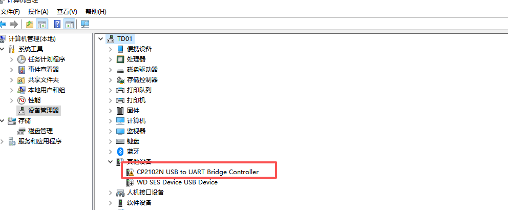
You need to download the driver program (CP2102), extract it, and install it.
[!NOTE]
- For Windows 64-bit systems, install the CP210xVCPInstaller_x64.exe program.
- For Windows 32-bit systems, install the CP210xVCPInstaller_x86.exe program.
- For macOS and other systems, search for the CP2102 driver in search engines.
Enter Configuration Mode
- Download and install a serial port assistant tool or other serial port debugging software.
- Connect the data transmission module to your computer via USB and open the serial port assistant software.
Method 1
- Select the USB COM port of the data transmission module, set the baud rate to 9600, data bits to 8, parity to none, stop bits to 1, and use ASCII for both transmission and reception.
- Use tweezers or similar tools to press and hold both the CONFIG and RESET buttons simultaneously. First release the RESET button, then release the CONFIG button.
Method 2
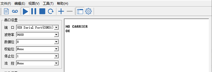
- Select the USB COM port of the data transmission module, set the baud rate to the current baud rate of the module (default is 57600 at the factory), data bits to 8, parity to none, stop bits to 1, and use ASCII for both transmission and reception.
- Send the following command:
+++
[!NOTE]
- Method 2 is recommended to use the SSCOM Serial Port Debug Assistant; some serial port assistants cannot send this command.
- Do not press the Enter key to wrap lines for this command.
- The serial port assistant will display the "NO CARRIER ok" prompt, indicating that you have entered the AT configuration mode successfully.
Enter the parameters in the serial port assistant and click Send to complete the configuration (each successful configuration will be followed by "ok").
[!NOTE] Each AT command requires pressing the Enter key to wrap lines (including the last command).
Common Configuration Commands
- Master: The communication-initiating device, usually used as the ground station. The RSSI indicator lights up only after the master receives data from the slave.
- Slave: The data-collecting device, usually used as the airborne station or receiving end. The RSSI indicator stays on after establishing communication with the master.
- Repeater: An intermediate device or node in the network, used to extend the communication distance between the master and the slave.
| Parameter Name | Function Description | Optional Values | Notes |
|---|---|---|---|
| +++ | Enter AT configuration mode | - | No Enter key required for this command |
| ATA | Exit AT configuration mode and enter data communication mode | - | - |
| AT&W | Save parameters | - | Send this command to save parameters during configuration |
| AT&V | Query module parameters | - | Used to query all current parameter configurations/firmware information |
| ATSxxx? | Query the current value of the ATSxxx parameter | - | - |
| ATSxxx=x | Set the value of ATSxxx | - | - |
| ATSxxx /? | Set the value of ATSxxx | - | Comment document for ATSxxx |
| AT&F10 | Default parameters for point-to-point Master | - | Default baud rate is 9600 after configuration |
| AT&F11 | Default parameters for point-to-point Slave | - | Default baud rate is 9600 after configuration |
| AT&F12 | Default parameters for point-to-point Repeater | - | Default baud rate is 9600 after configuration |
| AT&F7 | Default configuration for point-to-multipoint Master | - | Default baud rate is 9600 after configuration |
| AT&F8 | Default configuration for point-to-multipoint Slave | - | Default baud rate is 9600 after configuration |
| AT&F9 | Default configuration for point-to-multipoint Repeater | - | Default baud rate is 9600 after configuration |
| ATS133 | Communication mode | 0: Point-to-multipoint; 1: Point-to-point |
- |
| ATS101 | Working mode | 0: Master; 1: Repeater; 2: Slave |
- |
| ATS102 | Serial baud rate | 0: 230400; 1: 115200; 2: 57600; 3: 38400; 4: 28800; 5: 19200; 6: 14400; 7: 9600; 8: 7200; 9: 4800; 10: 3600; 11: 2400; 12: 1200; 13: 600; 14: 300 |
All devices in the network must use the same baud rate |
| ATS103 | Wireless transmission rate (air interface rate) | 0: 172800; 1: 230400; 2: 276480; 3: 57600; 4: 115200 |
Higher rates provide greater data bandwidth but reduce sensitivity/communication distance/stability |
| ATS108 | RF transmit power (mW) | 20: 100; 21: 125; 22: 160; 23: 200; 24: 250; 25: 320; 26: 400; 27: 500; 28: 630; 29: 900; 30: 1000 |
Higher transmit power results in longer communication distance |
| ATS104 | Network IP | 1 ~ 4294967295 (32-bit unsigned integer) | All devices in the communication network must have the same network IP |
| ATS105 | Local/Device address | 1 ~ 65535 | Each device in the same network must have a unique local address |
| ATS140 | Target device IP address | 1 ~ 65535 (65535 means broadcasting to all devices in the network) | Must be consistent with the device address of the communication peer (ATS105) |
| ATS141 | Repeater enable | 0: No repeater; 1: With repeater |
This parameter is available when the device is set as the master |
| ATS118 | Device IP to synchronize | 1: Default; 65535: Broadcast | - |
Point-to-Point Communication Configuration
For point-to-point mode, simply copy the parameters below, paste them into the serial port assistant, press the Enter key, and then click Send to complete the configuration (each successful configuration will be followed by "ok").
Master Settings (Ground Station)
- Set to master default settings and modify the baud rate to 57600.
AT&F10
ATS102=2
ATS104=725527
AT&W
AT&V
Slave Settings (Airborne)
- Set to slave default settings and modify the baud rate to 57600.
AT&F11
ATS102=2
ATS104=725527
AT&W
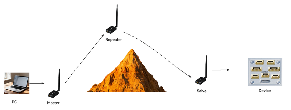
Point-to-Point Communication Configuration with Repeater
Master Settings (Ground Station)
- Set to master default settings and modify the baud rate to 57600.
AT&F10
ATS102=2
ATS104=725527
ATS141=1
AT&W
Slave Settings (Airborne)
- Set to slave default settings and modify the baud rate to 57600.
AT&F11
ATS102=2
ATS104=725527
ATS118=3
AT&W
Repeater Settings
- Set to repeater default settings and modify the baud rate to 57600.
AT&F12
ATS102=2
ATS104=725527
AT&W
[!NOTE] Adding a repeater to the network will halve the network's communication rate (throughput). When specifying that the slave connects to the master via a repeater, set the slave's ATS118 to 3. This ensures that the master and slave establish communication only when the repeater is involved. If you want the slave to connect through all devices in the network, set it to 65535. In this case, the slave will communicate directly with the master if possible, and the repeater effect can only be tested at long distances.
Point-to-Multipoint Communication Configuration
For point-to-multipoint mode, simply copy the parameters below, paste them into the serial port assistant, press the Enter key, and then click Send to complete the configuration (each successful configuration will be followed by "ok").
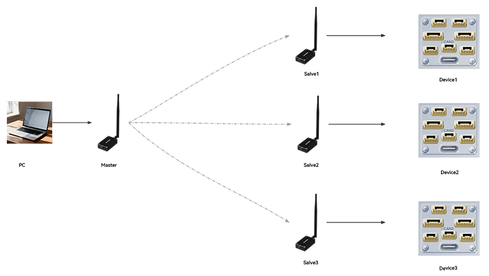
Master Settings
- Set to master mode, baud rate 230400, air interface rate 276480bps, network 725527, transmit power 1000MW, device address 1, target address 65535 (broadcast).
AT&F7
ATS102=0
ATS103=2
ATS104=725527
ATS108=30
ATS105=1
ATS140=65535
AT&W
Slave 1 Settings
- Set to slave mode, baud rate 230400, air interface rate 276480bps, network 725527, transmit power 1000MW, device address 2, target address 1 (master address).
AT&F8
ATS102=0
ATS103=2
ATS104=725527
ATS108=30
ATS105=2
ATS140=1
AT&W
Slave 2 Settings
- Set to slave mode, baud rate 230400, air interface rate 276480bps, network 725527, transmit power 1000MW, device address 3, target address 1 (master address).
AT&F8
ATS102=0
ATS103=2
ATS104=725527
ATS108=30
ATS105=3
ATS140=1
AT&W
Slave 3 Settings
- Set to slave mode, baud rate 230400, air interface rate 276480bps, network 725527, transmit power 1000MW, device address 4, target address 1 (master address).
AT&F8
ATS102=0
ATS103=2
ATS104=725527
ATS108=30
ATS105=4
ATS140=1
AT&W
Slave 4 Settings
- Set to slave mode, baud rate 230400, air interface rate 276480bps, network 725527, transmit power 1000MW, device address 5, target address 1 (master address).
AT&F8
ATS102=0
ATS103=2
ATS104=725527
ATS108=30
ATS105=5
ATS140=1
AT&W
[!TIP]
- For additional slaves, simply set
ATS105to a unique value in the network.- If connecting to an ArduPilot controller, set the controller's serial port baud rate to 230400 (
SERIALx_baud=230, where x is the serial port number) and ensureSYSID_THISMAVis set to a unique value.