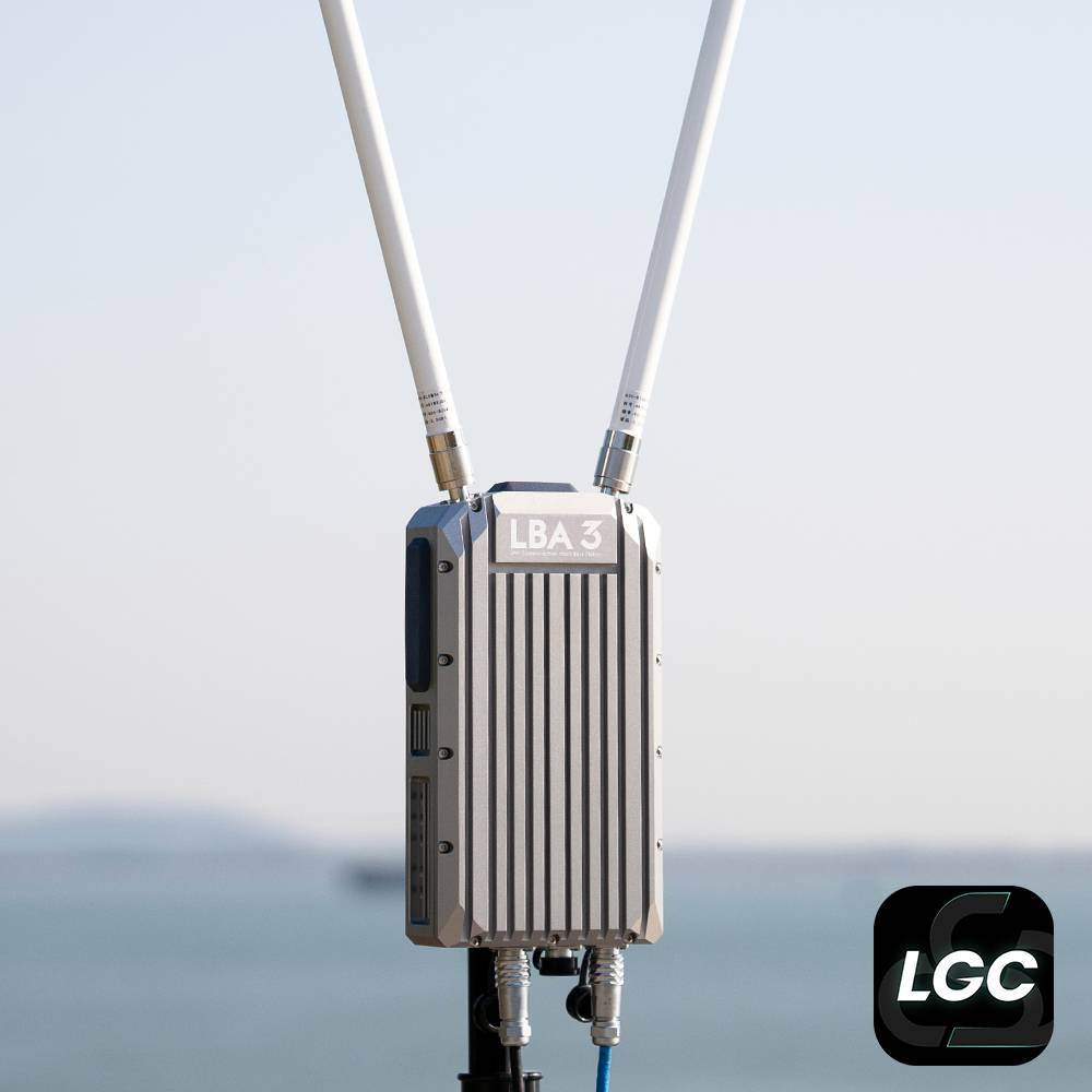
LBA3 Data and Video Transmission Systems
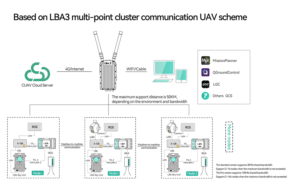
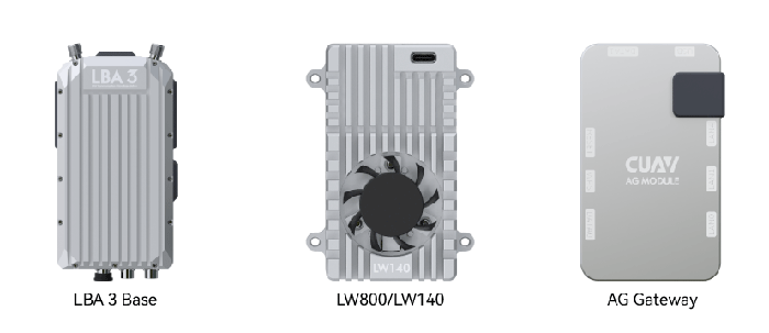
The LBA3 private network micro-base station system is a high-performance long-distance and large-bandwidth link system solution independently developed by Leixun Innovation.It consists of a LBA3 Base, an air terminal and an AG gateway.It has long-distance communication coverage capability and 30Mbps bandwidth. equipped with ground stations such as CUAV LGC, it can realize formation flight.
It is ideal for long-distance communication links for industrial unmanned systems equipment.
Feature
- Developed based on advanced LTE technology
- Long distance transmission
- 30Mbps large bandwidth, support star network
- AES encryption technology
- IP67 industrial three-proof design, no pressure for outdoor work
- Support cloud access and offline mode, expand infinite possibilities
- Support formation flight。
Parts
Purchase
Date Sheet
| Name | LBA3 BASE and LW140/800 |
|---|---|
| Technical standard | Based on LTE wireless communication standard |
| Anti-jamming | Dynamic frequency hopping, intelligent frequency hopping within the frequency band |
| Frequency band | 1.4G version:1420-1448MHz 800M version :806-826MHz |
| Transmit power | 33dBm(Typical value) |
| Bandwidth | default:20Mbps(10MHz);30Mbps(MAX,20MHz) |
| Operating Modes | Star network, point-to-point |
| Encryption | AES265 |
| Modulation | QPSK、16QAM、64QAM |
| Transmission delay | ≤150ms |
| Management interface | LBA3 BASE is managed by WEB LW140/800 is managed by AG (WEB) gateway |
| LTE network type | LBA3 BASE built-in full Netcom 4G module Support TD-LTE/FDD LTE/TD-SCDMA/WCDMA |
| Operating Voltage | LBA3 BASE:20~60V(Standard power consumption:24V 1.5A) POE module supports 100~240V Utility Power LW140/800:20~60V(Standard power consumption:24V 1A) |
| Operating temperature | -15~65℃ |
| Size | LBA3 BASE:220x120x50mm LW140/800:90x65x26.4mm |
| Weight | LW140/800:155g LBA3 BASE:1.65kg |
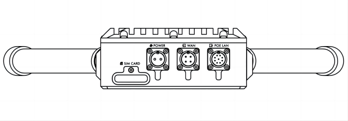
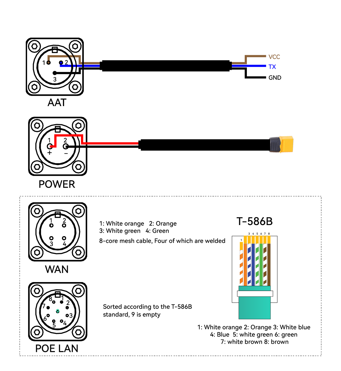
| Interface | LW140/800: Antenna(MCX-KE)x2 POWER(5023520200 to XT30)x1 RJ45x1(5025850470) UARTx1 USBx1 LBA3 BASE: N type antennax2、 Power(SF12 to XT60)x1 POE lan(SF12 to RJ45 Plug)x1 LAN(SF12 to RJ45 Plug)x1 AAT(SF12)x1 |
| Degree of protection | LBA3 BASE:IP67 LW140/800:IP20 |
| Name | AG Gateway |
|---|---|
| WIFI frequency band | 5G 20dbm |
| CPU frequency | 580MHz |
| RAM | 256MB |
| Operating Voltage | 4.8~5.2V(450mA) |
| Web management IP | Default IP (can be set):192.168.10.2(account:root, password: none) |
| Network frequency band | default (can be set):192.168.10.x |
| WIFI name | CUAV_AG_XXXX |
| WIFI account | 12345678 |
| Operating temperature | -15~60℃ |
| Storage temperature | -20~60℃ |
| Interface | LANx3、UARTx2、USBx1 |
Pinouts
LBA BASE
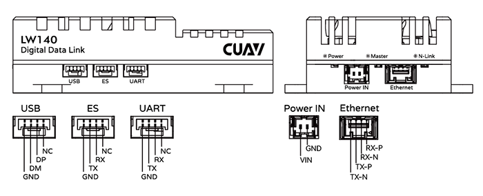
LW140/800
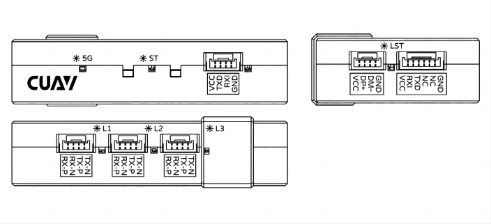
AG Gateway
Led indicator light
LBA BASE
LW140/800
- F-LED: Communication failure indicator light, when the key verification or re-connection fails, the light flashes or is always on.
- D-LINK: Slave communication status light, when the slave is connected to the master successfully, this light is always on
- Power: Power indicator light, always on when the power supply is plugged in
- Master: master status indicator, when configured as a master, this light is always on
- N-LINK: network port status indicator, when the network port is plugged in, it will flash alternately.
AG Gatewa
- LST indicator light: the LED is always on, indicating that the USB connection is detected
- LAN0/LAN2/LAN4 indicator light: always on means that LAN device access is detected, flashing means that data is being transmitted; off means no device is detected
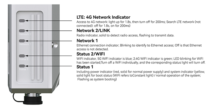
- WIFI indicator light: 5G WIFI indicator light, the LED flashes when WIFI is enabled, and when it is always on, it means entering the BOOT system
- System indicator: system indicator (yellow, always on for boot status (USB indicator is always on)/system normal operation status; blinking for system startup).
Hardware connection
Install LBA3 BASE
- Use a tripod to elevate the LBA3 BASE, use M4*8 screws to fix the quick release to the LBA3 BASE, and then install the quick release into the fixing rod.
- Install the antenna, install the antenna of the Type N interface to the LBA3 BASE.
[!NOTE] If the antenna is not installed to start the device, it may cause irreparable damage; please install the antenna before connecting the power supply; the tripod needs to be purchased by yourself, and a fixed rod with a diameter of 20~25mm is supported
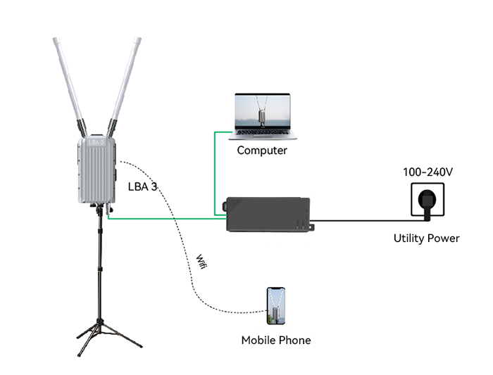
Power supply
1、Connect the POE power distribution module to Utility Power to provide power to the LBA3 base station.
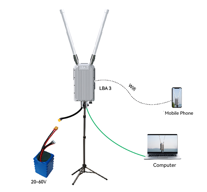
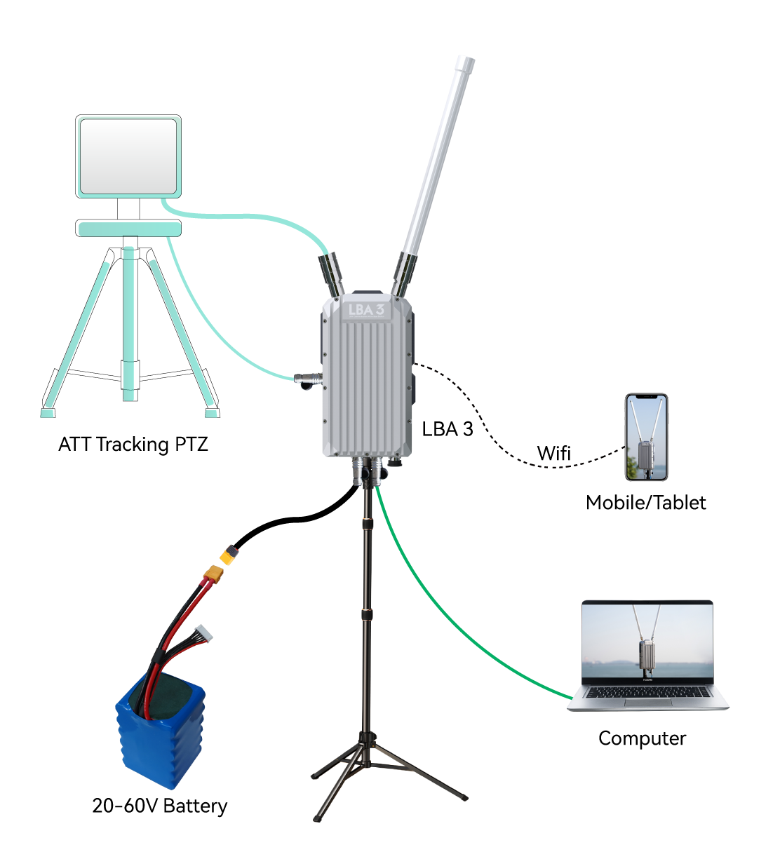
2、Power bank/battery (DC) power supply; support 20~60v.
AAT(Automatic tracking antenna)
Install the LW140/800 and AG module
- Insert the matching MCX feeder into the LW antenna interface, install the antenna to the drone, and install the antenna vertically upward or downward
- Connect the flight controller (TELEM1/2) to the AG DATE interface (AG-FC Cable)
- Connect the USB port of LW140/800 and AG gateway (USB cable)
- LW140/800 Ethernet interface is connected to AG gateway LAN0 interface (ETH-LAN0)
- Network port camera or ROS connected to AG gateway LAN1/LAN4
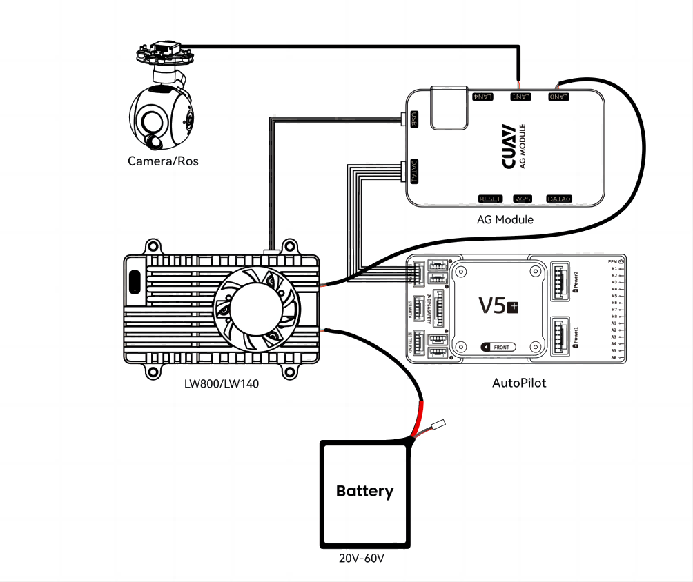
[!NOTE] The IP camera or ROS device needs to be in the same network frequency band as the LBA link (the IP address is 192.168.10.X and the IP address cannot conflict with other devices); you can follow the tutorial provided by the supplier or consult a technical engineer.
First time use
1、Connect to computer
- Wired broadband
Connect the LBA BASE to the computer with a network cable, and start the LBA BASE; in DHCP (Network Connection>Internet Protocol Version 4) is set to automatically obtain IP, and the computer will automatically recognize the LBA BASE network)
- WIFI
The LBA3 BASE WIFI name is LBA3_5G_xxxxxx (5G WIFI) and LBA3_xxxxxx
LW140/800 WiFI name is LBA3_AG_xxxxxx, and the default connection password is 12345678
2、Connect ground station
Take QGoundcontrol as an example
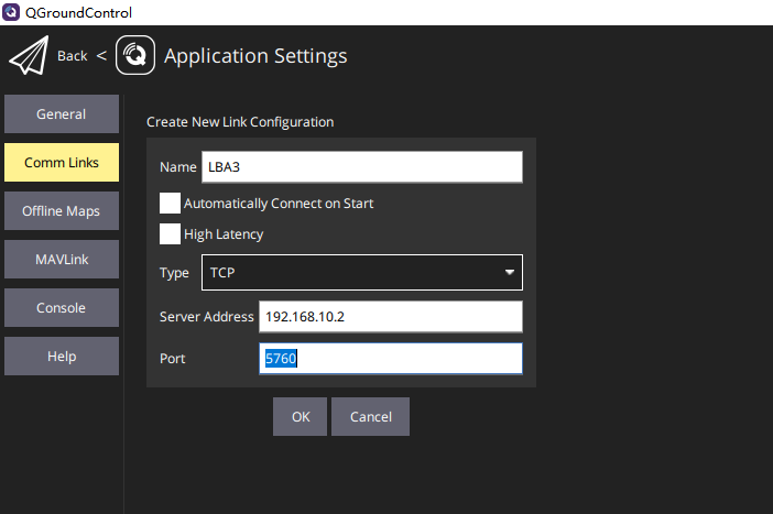
- New link in app settings(application settings>Comm links>add)
- Enter link name
- Select the connection type as TCP
- Enter AG gateway/LBA3 BASE IP
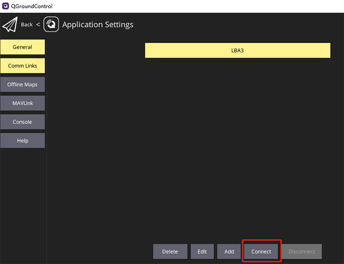
- Set the port "5760" (according to the setting) and click "OK"
- Select a new connection and click "connect"
2、Display video and control commands
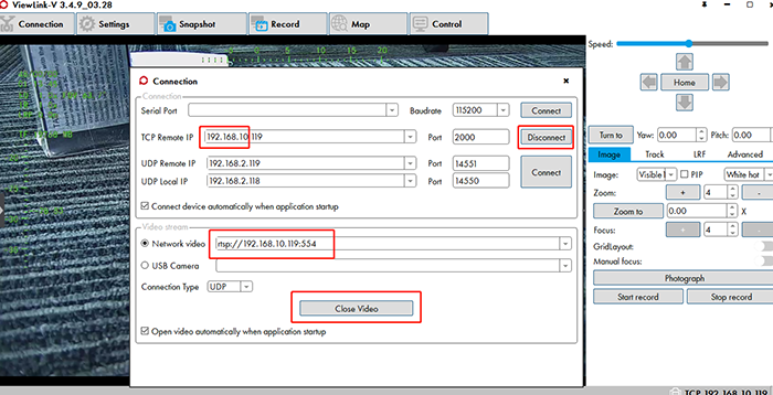
Display the video, use the program software provided by the supplier, and follow the supplier's tutorial to set up the connection
- Take a camera as an example
Enter the RTSP video stream address in the software: rtsp://192.168.10.119:554 (according to the actual IP setting of the camera, 192.168.10 is the network segment); establish a TCP connection, and control the pan/tilt and camera through the software.
System Topology
Point-to-point/point-to-multipoint communication system topology diagram

Topology diagram of multi-point UAV swarm formation system