Quick Wiring
This quick wiring guide describes how to power the 7‑Nano v2 and connect its most important peripherals.
Hardware Connection Overview
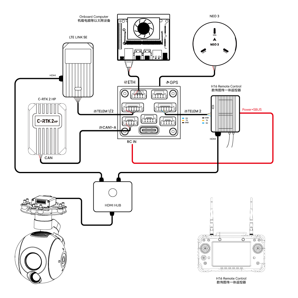
The diagram below shows the main peripheral connections for the 7‑Nano v2.
| Main Interface | Function & Purpose |
|---|---|
| POWER A | Connects to 7‑Nano PDB; supports power input and ADC voltage/current monitoring |
| M1~M14 | PWM signal outputs for motor or servo control; M1~M8 configurable for 5V PWM |
| RC IN | Connects remote receivers using unidirectional protocols such as SBUS / DSM / PPM (ELRS / CRSF receivers should be connected to any serial port, not RC IN) |
| RSSI | For connecting signal strength return modules |
| GPS&SAFETY | Connects to NEO series GPS or C‑RTK series RTK; integrates GPS, safety switch, and buzzer interfaces |
| GPS2 | Can be used to connect GPS / RTK |
| DEBUG | Used for FMU chip debugging and reading debug information; configurable as an extra serial port in ArduPilot |
| ADC | Includes ADC3.3 and ADC6.6 for analog voltage signal detection |
| TF CARD | Accepts SD card for flight log storage |
| ETH | Ethernet port for connecting to companion computers and other Ethernet devices |
| I2C | Connects external magnetometers and other I2C devices for communication between the controller and I2C peripherals |
| TELEM1/TELEM2 | Connects telemetry modules for MAVLink data communication |
| CAN1‑A/B | For communication between the controller and CAN devices (e.g. NEO3 pro GPS) |
| CAN2 | For communication between the controller and CAN devices (e.g. NEO3 pro GPS) |
| TYPE C | USB port for connecting to ground station, firmware flashing, etc. |
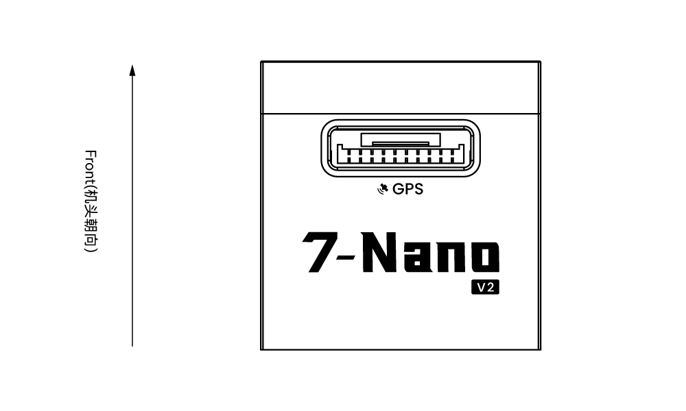
Forward Orientation
[!NOTE] By default, the arrow points to the front of the aircraft. Ensure the arrow faces forward during installation. If the controller cannot be installed in the recommended orientation (e.g. space constraints), configure the controller orientation in firmware (PX4 firmware here, ArduPilot firmware here).
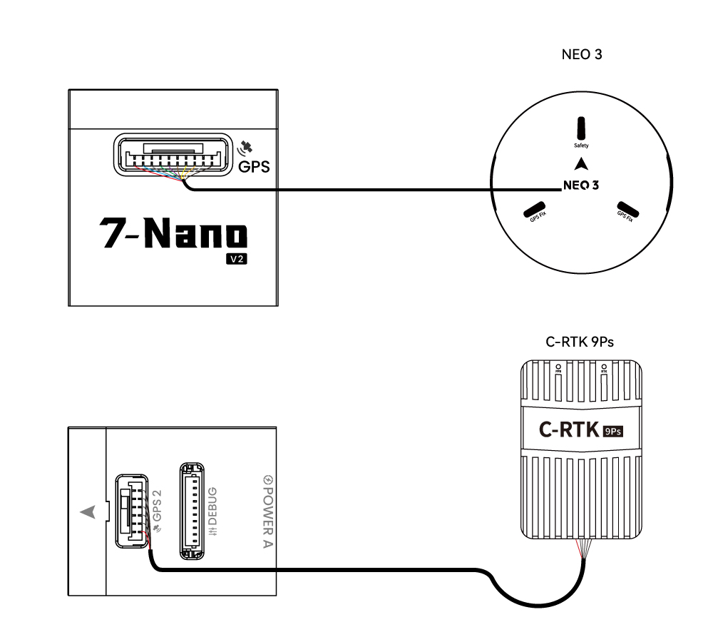
GPS Positioning System
We recommend using a CAN GPS/RTK (such as NEO 4se), which can be connected directly to CAN1/CAN2. You may also use a standard GPS/RTK module connected to the GPS&SAFETY port. Most modern GPS modules integrate GPS, compass, safety switch, buzzer, and status LED. The GPS module should be mounted on a bracket, away from other electronic equipment, and oriented toward the front of the aircraft (NEO GPS arrow aligned with the controller arrow).
Safety Switch & Buzzer
[!NOTE] When using a NEO series GPS, no extra safety switch or buzzer is required.
If flying without a GPS module, you must connect the safety switch directly to the GPS&SAFETY port to arm and fly the drone. (For legacy 6‑pin GPS modules, refer to the pinout definition at the bottom for wiring modification.)
Remote Control Receiver
For flight safety, we recommend connecting a remote controller for both manual and autonomous flight (for emergency manual takeover). Wiring methods vary by receiver type:
Android Remote Controller (H16 as example)
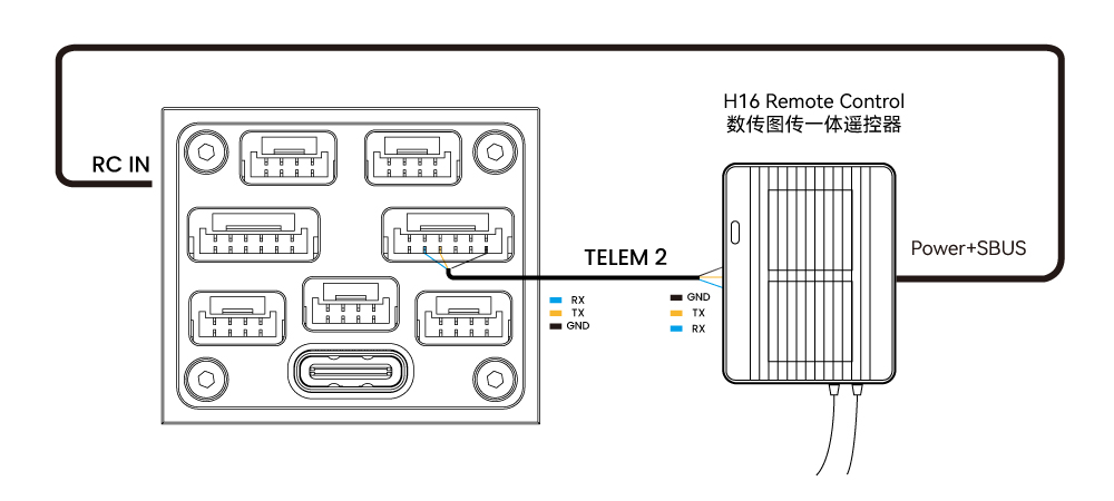
- Connect 7‑Nano TELEM1/TELEM2 to H16 UART0, and H16 SBUS pin to the RC port on the side of the 7‑Nano.
SBUS/DSM/PPM Unidirectional Receivers
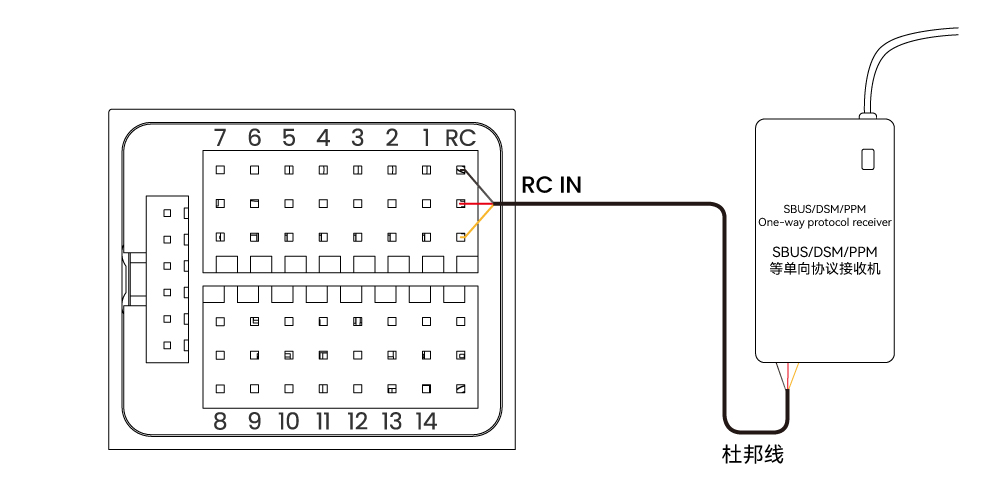
- Use jumper wires to connect the receiver to the side RC port.
ELRS/CRSF Receivers
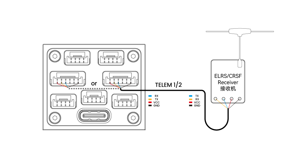
- Connect ELRS/CRSF receiver to any UART serial port on the 7‑Nano (e.g. TELEM2) and configure parameters in ArduPilot or PX4.
Power Supply
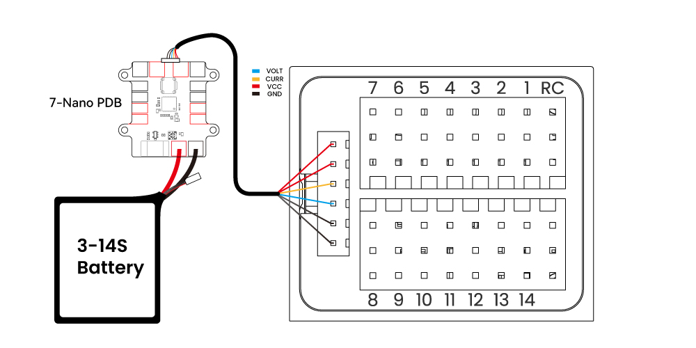
PDB Kit
Standard Kit
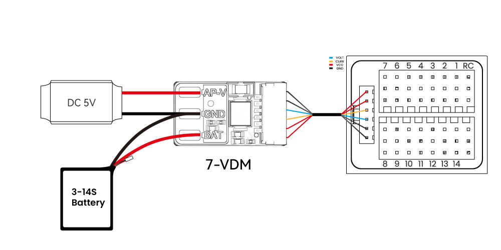
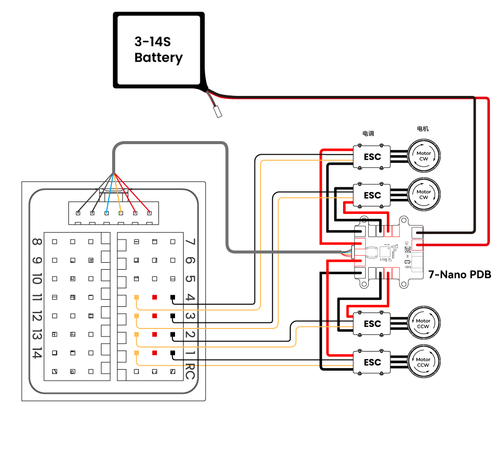
[!NOTE] The standard kit includes a 7‑VDM power detection module and requires an additional 5V BEC to power the controller. The PDB kit includes a 7‑Nano PDB power module with integrated BEC, voltage/current monitoring, and power distribution.
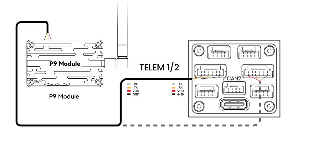
Telemetry System
A telemetry system allows communication between the ground station software and the drone for real‑time monitoring and control. The airborne telemetry module should be connected to TELEM1/TELEM2.
SD Card
The 7‑Nano v2 comes pre‑installed with an SD card; no additional installation is needed.
Motors
Connect motors/servos to ports M1~M14 according to the recommended order for your aircraft frame.
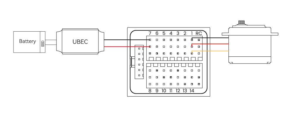
Servo Power Supply
The servo ports on the 7‑Nano v2 are fully isolated from the controller’s internal power and do not supply power to servos. To power servos, connect a BEC to any positive/negative rail of M1~M14 (all channels share common power), then plug in the servos.