Quick Wiring
This quick wiring guide explains how to power the X25 EVO intelligent controller and connect its most critical peripheral devices.
Hardware Connection Overview
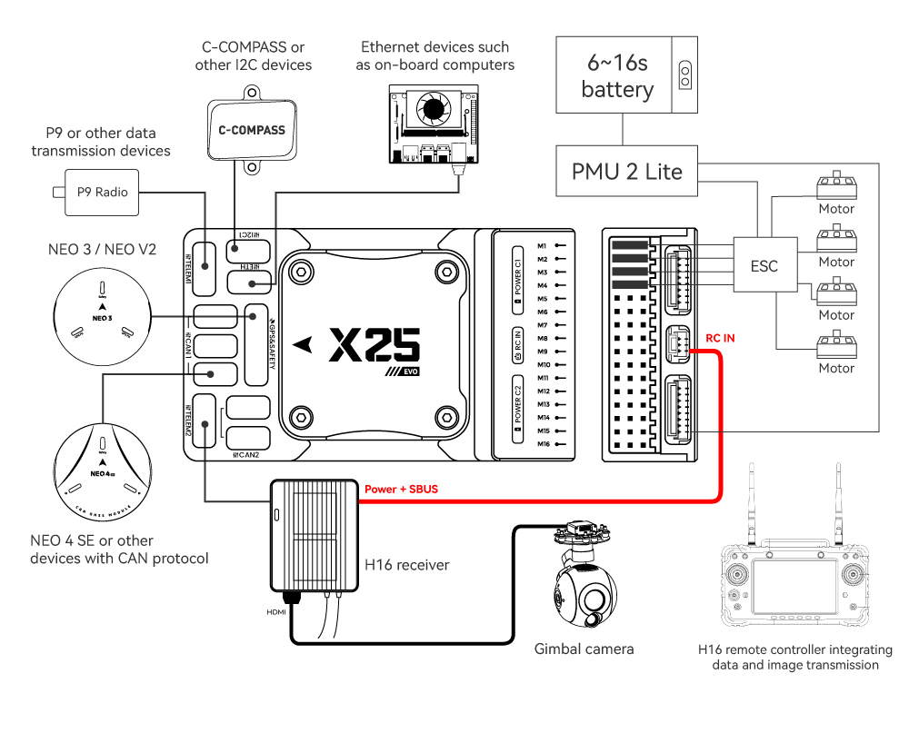
The figure below shows the connections for the most important peripherals of the X25 EVO.
| Main Ports | Function & Purpose |
|---|---|
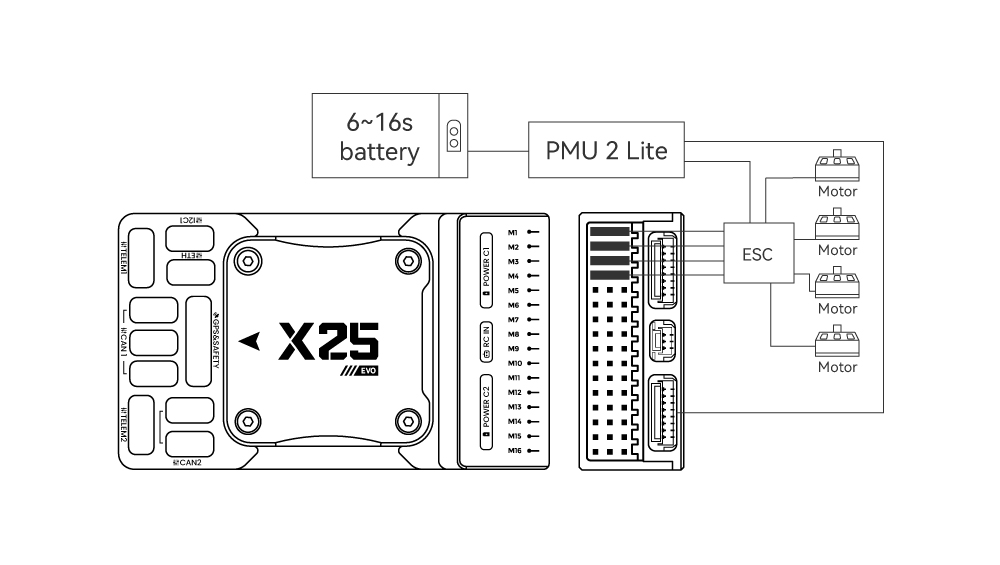
| POWER C1/C2 | Connect the PMU2 Lite to this port; this port is used for connecting the DroneCAN power module. |
| M1~M16 | PWM signal output ports, usable for controlling motors or servos; support 3.3V/5V PWM configuration. |
| RC IN | Connect remote controller receivers with one-way protocols (e.g., SBUS/DSM/PPM). Note: ELRS/CRSF receivers should be connected to any serial port, not RC IN. |
| RSSI | For connecting signal strength feedback modules. |
| GPS&SAFETY | Connect Neo-series GPS or C-RTK-series RTK; this port includes interfaces for GPS, safety switch, and buzzer. |
| GPS2 | Usable for connecting additional GPS/RTK modules. |
| DEBUG (DSU) | For FMU chip debugging and reading debug device information; with ArduPilot firmware, it can be configured for other serial port functions. |
| ADC3V3 | For analog level signal detection; the maximum detectable level signal is 3.3V. |
| ADC6V6 | For analog level signal detection; the maximum detectable level signal is 6.6V. |
| TF CARD | Insert an SD card here to enable log storage functionality. |
| ETH | Ethernet port, usable for connecting Ethernet devices such as companion computers. |
| I2C1/2/3 | Connect external I2C devices (e.g., external compasses) for communication between the controller and I2C devices. |
| TELEM1/TELEM2 | Connect telemetry modules (for data transmission) to enable MAVLINK data interaction. |
| CAN1/2 | For communication between the controller and DroneCAN devices (e.g., connecting NEO4 SE GPS). |
| TYPE C | USB port of the controller, usable for connecting to the ground station, flashing firmware, and other operations. |
| SPI6 | SPI port for external expansion; generally not used. |
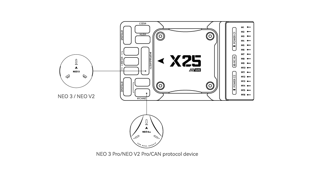
GPS
We recommend using a CAN GPS/RTK (such as Neo 4SE); simply connect it to the CAN 1 or CAN 2 port. You can also use a standard GPS/RTK module by connecting it to the GPS&SAFETY port.Most commonly used GPS modules today integrate GPS, compass, safety switch, buzzer, and LED status light. Mount the GPS module on a bracket, keep it away from other electronic devices, and align it with the aircraft’s forward direction (the arrow on the NEO GPS should match the arrow on the flight controller).
Safety Switch & Buzzer
[!NOTE]
When using a NEO-series GPS, no additional safety switch or buzzer is required. The safety switch acts as a motor safety lock—long-press the white button on the GPS to arm or disarm the motor.For PX4 firmware: The safety switch is disabled by default.For ArduPilot firmware: Disable the safety switch by setting the BRD_SAFETY_DEFLT parameter to 0.
Remote Controller
Connection methods vary by remote controller and receiver type:
Android Remote Controllers
Take the H16 as an example:
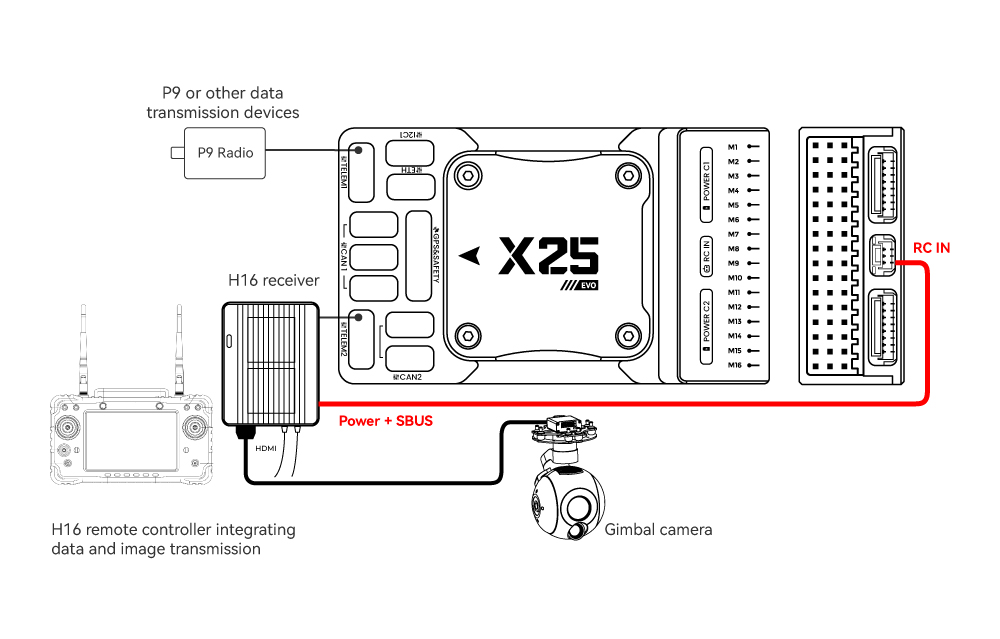
- Connect TELEM1/TELEM2 to the UART0 port of the H16 remote controller, and link the H16’s SBUS pin to the RC IN port.
SBUS/DSM/PPM Protocol Receivers
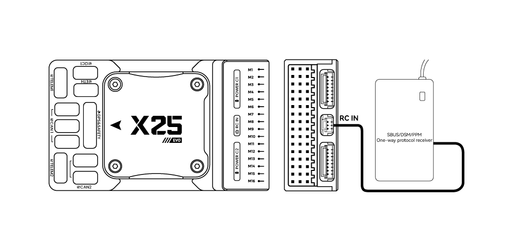
- Use wires to connect the receiver to the RC in port at the rear of the controller.
ELRS/CRSF Receivers
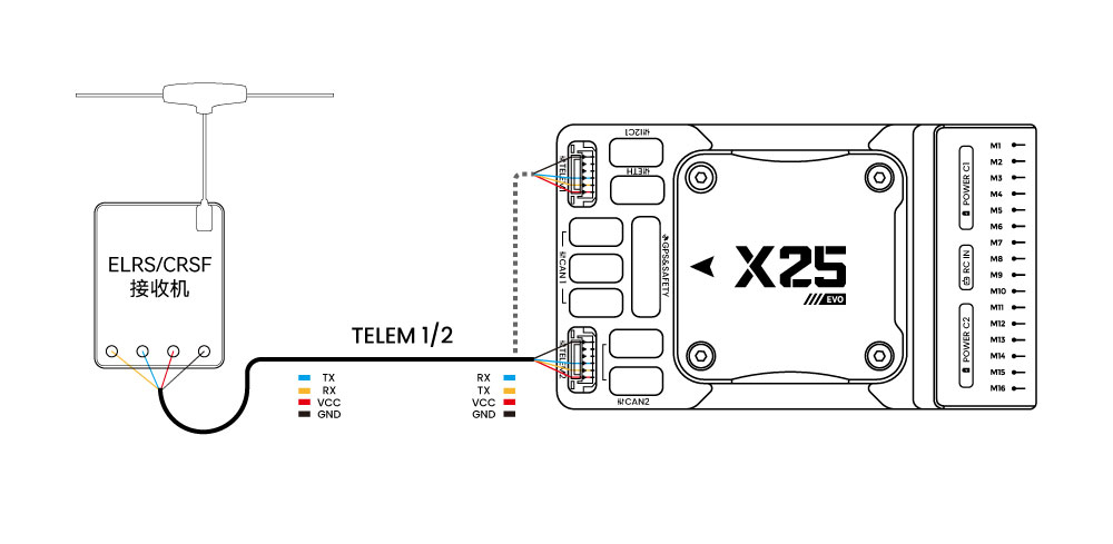
- Connect the ELRS/CRSF receiver to any UART serial port of the X25 EVO (e.g., TELEM2)and Modify the corresponding parameters for ArduPilot /PX4.
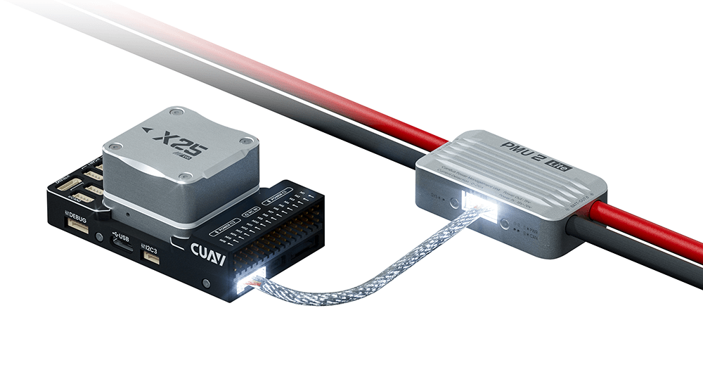
Power module
The X25 EVO comes standard with the PMU2 Lite power module, which supports 20–70V input and can measure a maximum current of 220A. It can be directly connected to the Power C1/C2 port of the X25 EVO and is plug-and-play (no configuration required).
Telemetry
A telemetry system allows you to communicate with the unmanned system via ground station software, enabling you to monitor and control the UAV’s status during flight. Connect the on-board unit of the telemetry system to the TELEM1 or TELEM2 port.
SD Card
The SD card is pre-installed at the factory—no additional installation is needed on your part
Motors
Connect motors/servo systems to the M1~M16 ports in the order specified for your aircraft in the airframe reference document.
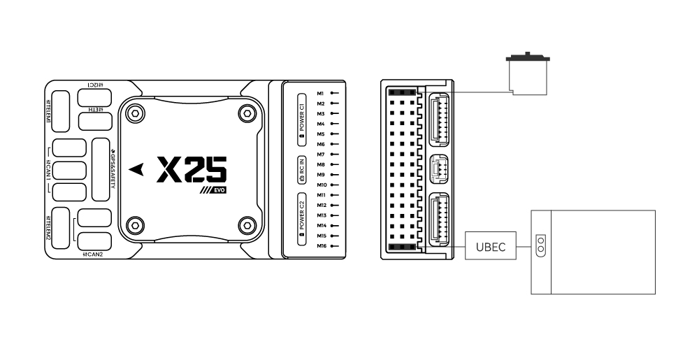
Servo Power Supply
The X25 EVO does not supply power to servos. If you need to power servos:
- Connect a BEC to the positive and negative terminals of any column among M1~M16 (the positive and negative terminals of M1~M16 are interconnected).
- Then connect the servos to the same column.