CAN PDB
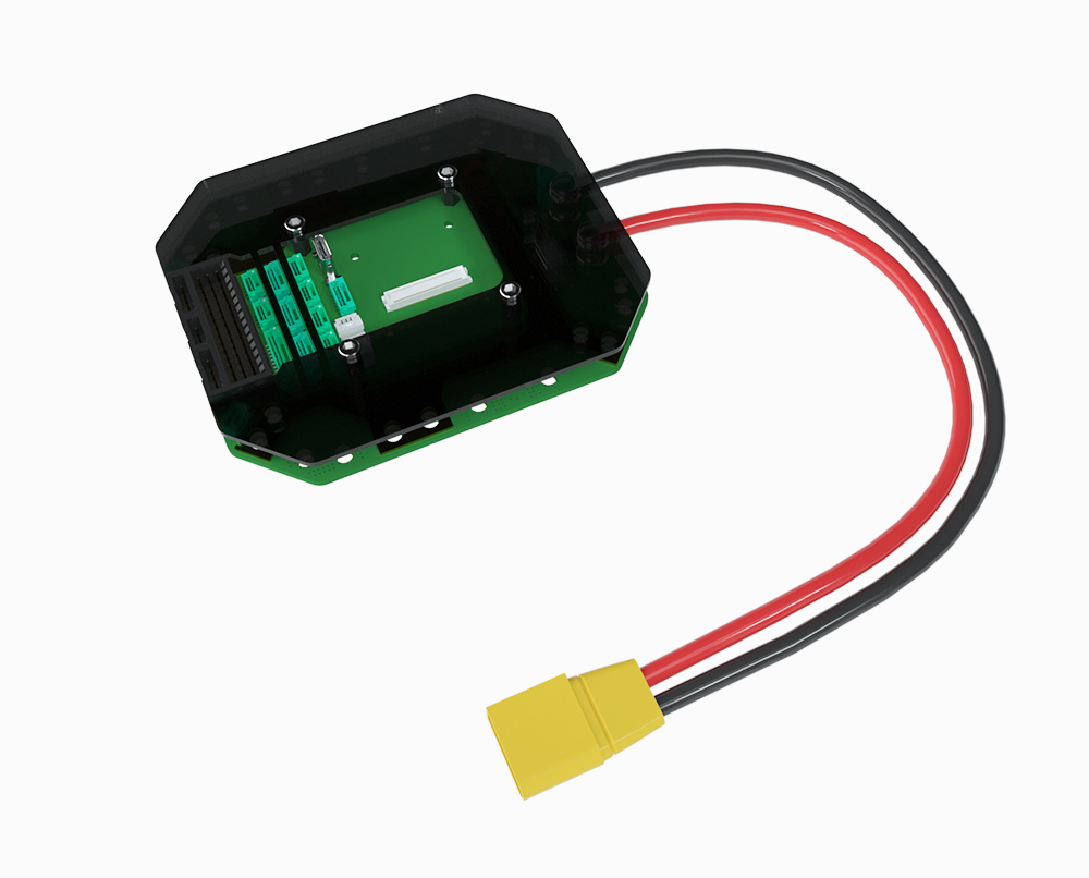
CAN PDB is an autopilot carrier board developed by CUAV. It integrates the power distribution board, Dronecan intelligent power management system, and autopilot carrier board.
The ultra-thick copper and tin PCB can provide up to 110A of continuous operating current for any device. The self-developed TTI algorithm achieves 0.1A current and 0.05V voltage measurement accuracy comparable to precision instruments.
Feature of product
1.Configurable servo voltage output (5V/7.4V/8.2V), which can power servos with common specifications for unmanned systems.
2.Supports 5V PWM (when K1 is turned on) to improve the anti-interference ability of the control signal.
3.Supports 14~62V voltage input.
- Accurately measure voltage and current, current accuracy is 0.1A within 110A, and voltage accuracy is 0.05V.
5.Droncan intelligent power management system intelligently monitors battery power, voltage and current.
6.Ultra-thick copper and thickened tin-plated PCB can effectively reduce the heat caused by the internal resistance of the circuit under high current.
7.10 channels of main power output with low voltage drop. 8.Run the TTI algorithm to improve the accuracy of power supply detection under various temperatures.
Data sheet
| Data sheet | |
|---|---|
| MCU | STM32F4 |
| Operating Voltage | 14-62V(4-15S Lipo) |
| Detection current range | 0-110A |
| Output power(MAX) | 6000W(continued 120s) |
| Stable output power(MAX) | 5500W |
| Core | V5+/X7/X7 Pro/X7+/X7+ Pro |
| Frame type | Planer/VTOL/Copter/ helicopter/Rover/sub/ |
| Autopilot firmware | ArduPilot 4.0.0 and above firmware Px41.11.0 and above firmware |
| Operating temperature | -20~+100℃ |
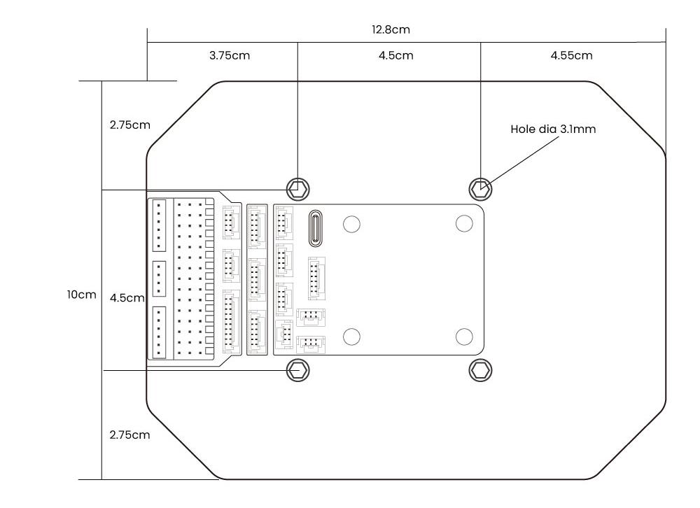
| Size | 12.8cm (length) × 10cm (width) × 1.2cm (height) (The height after installing X7+/X7+PRO is 4.5cm The height after installing V5+ is 3.9cm) |
| Weight | 200g (including cable) |
| Wire length | 30cm |
| Interface | |
| V_OUT | 5V(default)/7.4V/8.2V(4A) |
| Servo VCC | 5V(default)/7.4V/8.2V(8A) |
| 12V OUT | 4A(max) |
| USB | 1 |
| UART1 | 5(gps/uart4/telem1/telem2/debug) |
| CAN | 2 |
| I2C | 3 |
| SBUS/DSM IN | 1 |
| PPM IN | 1 |
| Servo | 14 |
| ADC3.3 | 1 |
| ADC6.6 | 1 |
| SBUS outs | 1(This interface is invalid when using X7+/X7+pro core) |
| RSSI | 3.3V(Analog input) |
| DSU7 | 1 |
Size
LED status light
- Flashing green: Each battery voltage is 4.0~4.3V
- Flashing yellow: The voltage of each battery is lower than 4.0V but higher than 3.7V
- Flashing red: the voltage of each battery is lower than 3.5v
[!NOTE] Determine the number of battery cells based on the initial voltage. When you power on, the voltage of each LiPo cell is lower than 3.7V, which may misjudge the number of battery cells.
Pinouts
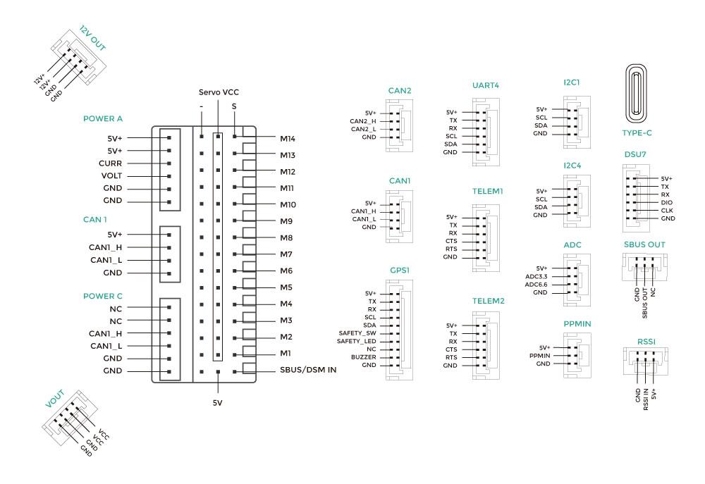
[!TIP] The pin definition diagram is consistent with the actual interface location.
VOUT and Servo VCC
If you need CAN PDB to power equipment such as fixed-wing servos, please solder JP1, which will connect the VOUT circuit to obtain 5V/7.4V/8.2V power supply.
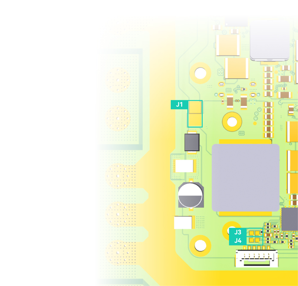
[!NOTE] JP1/JP3/JP4 are disconnected by default. At this time, Servo_vcc (black box in the picture) is an independent circuit and the voltage is 0V. When JP1 is welded, Servo_vcc is connected to the VOUT circuit, and the voltage is 5V; when JP3 is welded, the VOUT circuit voltage becomes 7.4V; when JP3 and JP4 are welded, the VOUT circuit voltage becomes 8.2V.
5V PWM
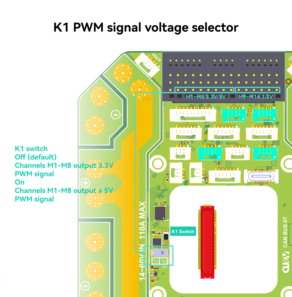
[!Tip] If ESC supports 5V PWM, turn on the K1 switch, and the autopilot M1-M8 will output a 5V PWM signal, which can effectively improve the anti-interference ability.