Ardupilot User Guide
This chapter will describe how to run ArduPilot on Pixhawk V6X®.
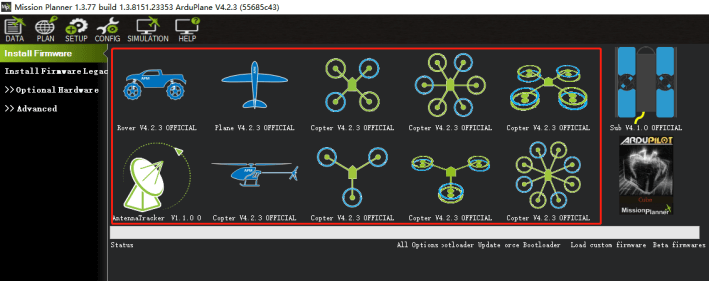
load firmware
[!NOTE] ArduPilot firmware 4.23 and above is perfectly compatible with Pixhawk V6X®.
Online burning firmware:
- Connect the flight controller to the computer,
- open the ground station
- click the "SETUP" "install firmware" >select the firmware type you need"
- wait for the burning to complete.
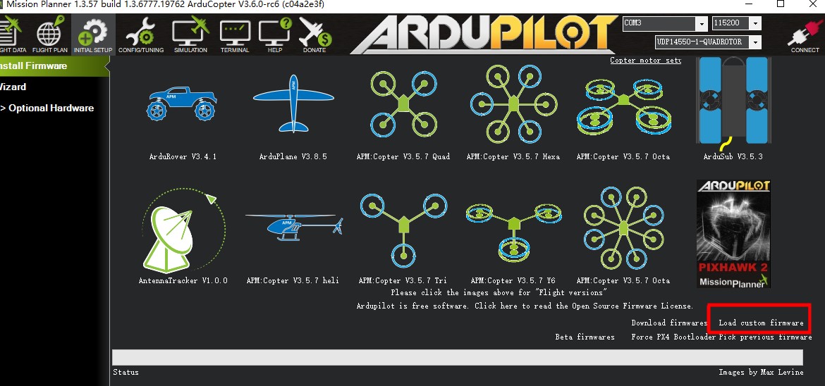
Load local firmware
Please download the firmware to the local first:
Plane(and VTOL)
- Select to load custom firmware
- select local firmware file
UART MAP
- SERIAL0 -> USB
- SERIAL1 -> UART7 (Telem1) (Contains CTS and RTS )
- SERIAL2 -> UART5 (Telem2) (Contains CTS and RTS)
- SERIAL3 -> USART1 (GPS1)
- SERIAL4 -> UART8 (GPS2)
- SERIAL5 -> USART2 (Telem3)(Contains CTS and RTS)
- SERIAL6 -> UART4(User)
- SERIAL7 -> USART3(Debug)
- SERIAL8 -> USB(MAVLink, can be used for SLCAN with protocol change)
RC input
Use a special cable (the cable has a label) to connect the remote control receiver. The SBUS/DSM receiver is connected to the DSM/SBUS interface, and the PPM receiver is connected to the PPM interface; for CRSF and the receiver with the telemetry bidirectional protocol, it needs to be connected to the UART interface, such as Serial6 (UART4).
Here is the setup tutorial:
- SERIAL6_PROTOCOL set to 23;
- FPort:SERIAL6_OPTIONS set to 15;
- CRSF:SERIAL6_OPTIONS set to 0;
- SRXL2:SERIAL6_OPTIONS set to 4,And only connect the TX pin.
[!NOTE] Any UART can be used for RC system connections in ArduPilot also, and is compatible with all protocols except PPM. See Radio Control Systems for details.
PWM Output
Pixhawk V6X® supports up to 16 PWM outputs (M1~M8, A1~A8). All 16 outputs support all normal PWM output formats. A1~A8 support DShot and BDshot.
The 8 FMU PWM outputs are divided into 4 groups:
- A1~A4 in group1
- A5~A6 in group2
- A7~A8 in group1
[!NOTE] FMU outputs within the same group need to use the same output rate and protocol. If any output in a group uses DShot, then all outputs in that group are Dshot.
GPIOs
A1~A8 can be used as GPIO (relay, button, RPM, camera shutter trigger (level), etc.). To use them, you need to set the output SERVOx_FUNCTION to -1 (GPIO).
The numbering of the GPIOs for PIN variables in ArduPilot is:
FMU pins:
- A1:50
- A2:51
- A3:52
- A4:53
- A5:54
- A6:55
- A7:56
- A8:57
Others GPIO:
- FMU_CAP1:58
- NFC_GPIO:59
Analog inputs
Pixhawk V6X® has 3 analog inputs (ADC6.6V、ADC3.3V、Rssi)
- ADC6.6-> 12
- ADC3.3-> 13
- RSSI-> 103
Battery Monitoring
Pixhawk V6X® comes standard with CAN PMU lite ammeter (Dronecan), please connect it to Power C1/Power C2 instead of Power 1/Power2 (I2C/SMBUS)
You need to set the following parameters:
- BATT_MPNITOR=8
- CAN_P1_DRIVER=1
- CAN_P2_DRIVER=1
[!NOTE] Do not attempt to set up the I2C power monitor for the Pixhawk V6X using the Mission Planner SETUP-> optional hardware > battery monitor tab.
Analog power monitor
Digital power modules are more accurate and reliable(such as CAN PMU lite), Pixhawk V6x is not recommended to use analog power modules; If you do need to use it, connect the hardware as shown(Take HV_PM as an example):
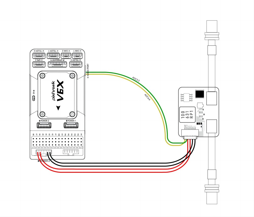
You need to set the following parameters in the Mission Plannner parameter table:
- BATT_MONITOR=4
- BATT_VOLT_PIN=12(ADC6.6)
- BATT_VOLT_MULT=18(HV_PM)
- BATT_CURR_PIN=13(ADC3.3)
- BATT_AMP_PERVLT=24(A/V,HV_PM)
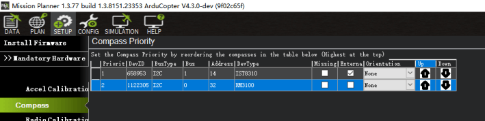
Compass
Inside the Pixhawk V6X® is an RM3100 magnetic compass. Generally, the flight control is located inside the drone, and the magnetic field environment is more complicated. It is reasonable to use an external compass (such as one on a GPS) as the primary compass; always ensure that the external compass is placed in preference to the internal compass.
If your compass is set up like this:
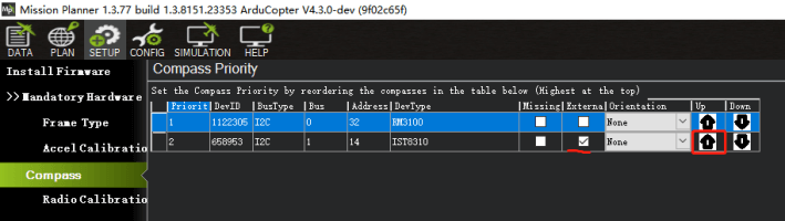
Please set the external compass as the first compass according to the following figure.
I2C Protocol hardware
The Pixhawk V6X kit includes a UART->I2C cable and CAN/I2C interposer board for transferring I2C devices (e.g. MS5525 airspeed meter, LED status light, etc).
Ethernet Setup
[!TIP] ArduPilot 4.5 and above supports Pixhawk v6x Ethernet.
Open Mission planner>Config>Full parameters list, set NET_ENABLED=1, restart the autopilot and modify the following parameters:
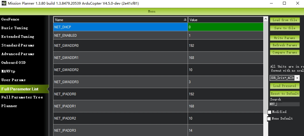
As shown above, set the autopilot IP to 192.168.10.14 and the gateway IP to 192.10.3
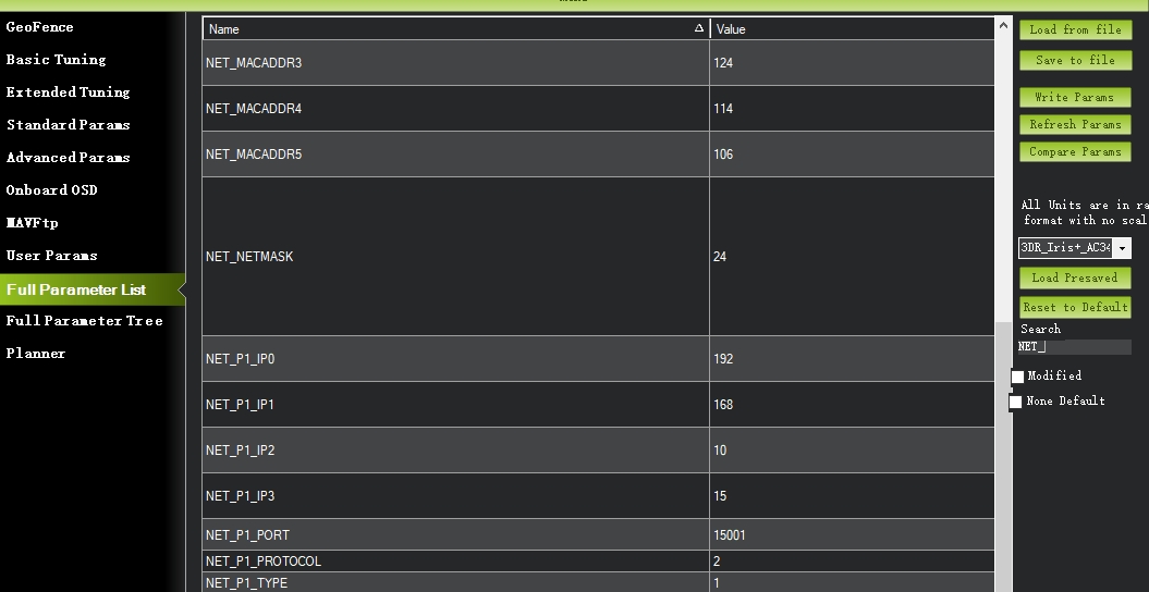
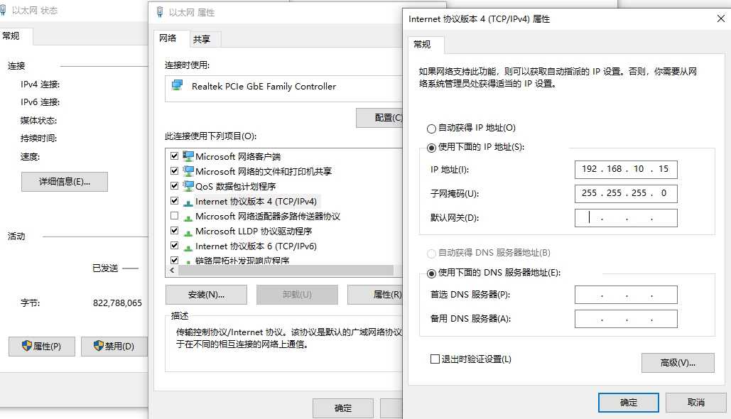
Set the computer IP to 192.168.10.15, set a network port to 15001 to access the network device through UDP, and the port protocol is 2.
[!NOTE] Up to four ports can be configured.
Hardware connection
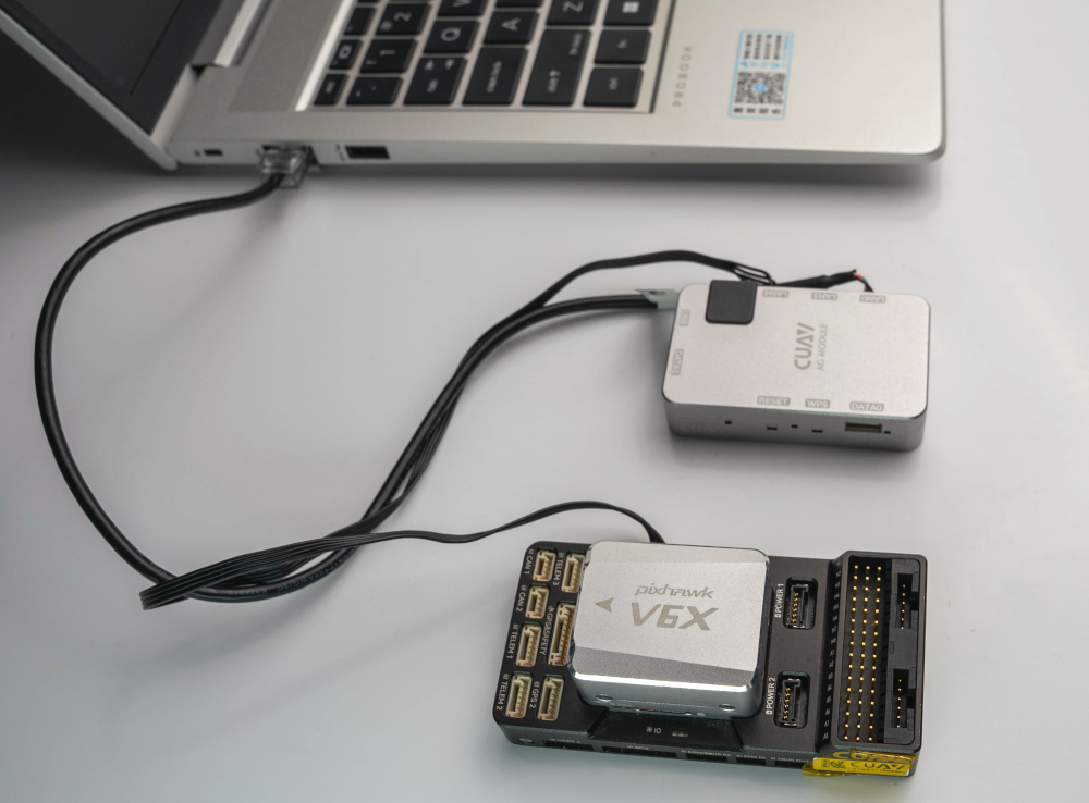
- Use the network cable provided by Pixhawk V6X to connect Pixhawk v6X to the computer and power the autopilot and AG router.。
- Enter the computer [Change Network Adapter Options]>Ethernet Properties [Internet Protocol Version 4 (TCP/IPV4]]> Manually configure the network (local IP, configured as 192.168.0.1, subnet mask 255.255.255.0)> click OK to apply Configuration
Network Connectivity Test
- Enter the Windows command window
- ping 192.168.10.4
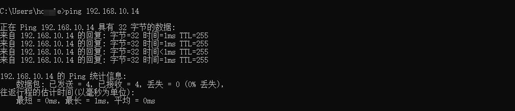
[!TIP] If there is a network delay data reply, the communication is established. If the communication timeout is displayed, the IP may be incorrect or the communication failed.
Connect to Mission planner
- Run Mission planner ground station software
- Set the connection method "UDP"
- port number 15001
Building ArduPilot Firmware
./waf configure --board Pixhawk6x
./waf copter --upload
[!NOTE] Most users do not need to compile firmware. They can directly write firmware online through the ground station.