C-RTK2 HP User Guide(Ardupilot)
[!NOTE] C-RTK 2HP supports connecting to the controller via CAN (DroneCAN) and UART. It is recommended to use CAN. Before configuration, you need to fix the two antennas and keep a distance of more than 30cm and maintain an open view of the sky. Do not get close to windows or other obstructions, otherwise you may not be able to obtain heading data.
Hardware connection
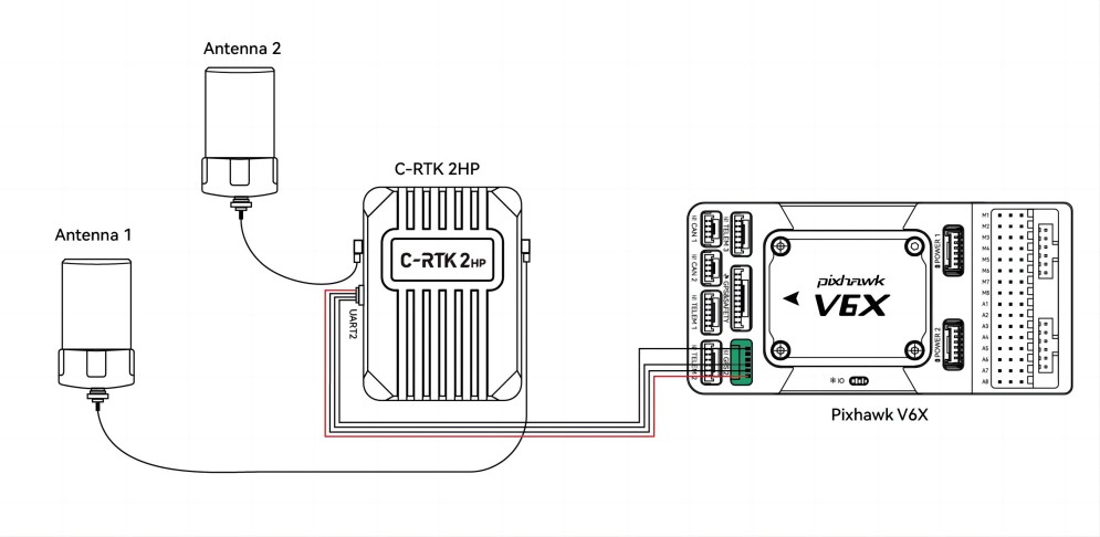
C-RTK2 HP supports connection in the following ways (choose one of the two)
CAN(Recommend)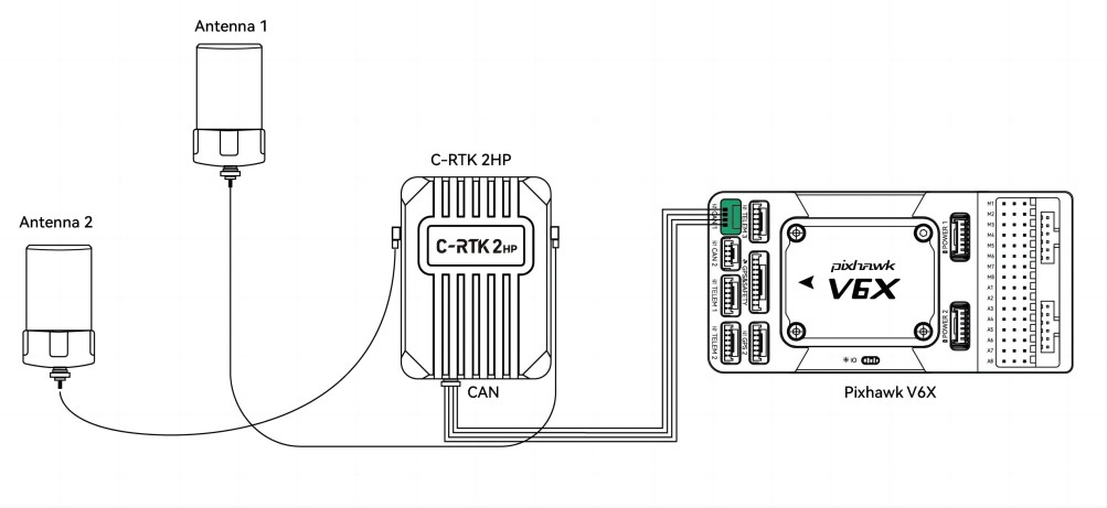
UART
Enable C-RTK2 HP
Set the following parameters in the Missionplanner/Configuration Assistant/All Parameters table:
GPS_TYPE = 9(droncan:9;UART:25)or GPS1_TYPE=9(AP4.6.0 and above version firmware)
CAN_P1_DRIVER=1(CAN1)
EK3_SRC1_YAW = 2 or 3(heading source, 2: use GPS haeding. 3: use GPS first, compass as backup)<
GPS_AUTO_CONFIG=2(Automatically configure Dronecan GPS)
[!TIP] When you configure the drone by importing the parameter file, please check whether the following parameters have been modified. Haeding only works when AHRS uses EKF3 as source of attitude and position estimation.
AHRS_EKF_TYPE=3
EK3_ENABLE=1
Master and slave antenna offset
- GPS_MB1_TYPE=1(GPS1 Moving Baseline master antenna offsets relative to slave antenna, also enables the next parameters to be shown)
- GPS_MB1_OFS_X:offset in meters from the “Slave” to “Master” antenna in the X axis (in direction of 0 deg yaw, positive offsets are if “Master” is in front of the “Slave”.
- GPS_MB1_OFS_Y:offset in meters from the “Slave” to “Master” antenna in the Y axis (in direction 90 deg (right) of 0 deg yaw, positive offsets are if “Master” to the right of the “Slave”.
- GPS_MB1_OFS_Z:offset in meters from the “Slave” to “Master” antenna in the Z axis (in direction up and down, positive offsets are if “Master” below the “Slave”.
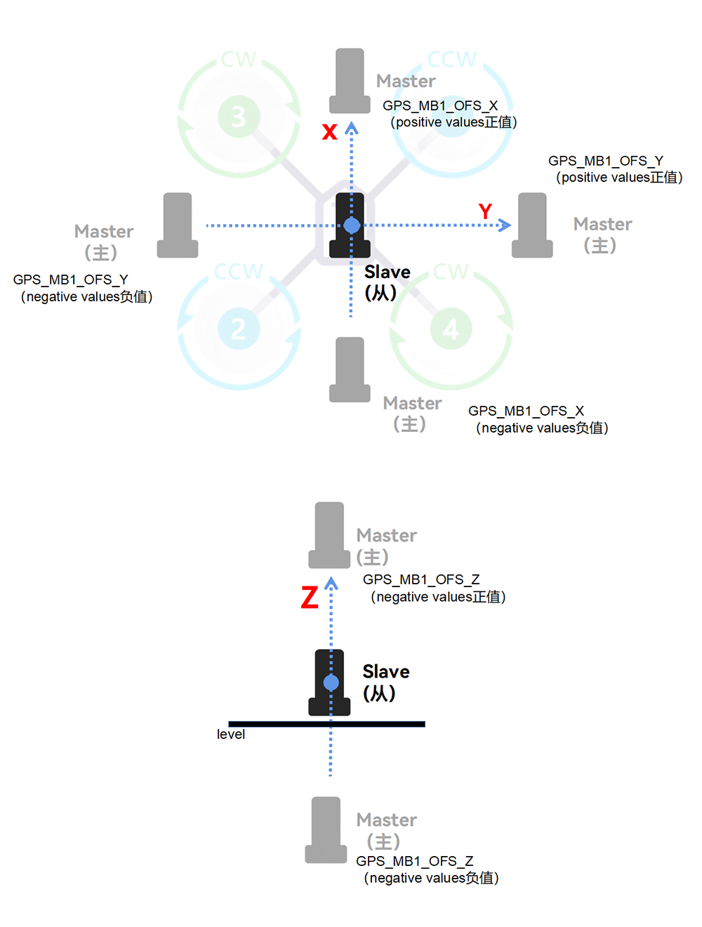
For firmware version 4.6.0 or above
- GPS1_MB_TYPE=1(GPS1 Moving Baseline master antenna offsets relative to slave antenna, also enables the next parameters to be shown)
- GPS1_MB_OFS_X:offset in meters from the “Slave” to “Master” antenna in the X axis (in direction of 0 deg yaw, positive offsets are if “Master” is in front of the “Slave”.
- GPS1_MB_OFS_Y:offset in meters from the “Slave” to “Master” antenna in the Y axis (in direction 90 deg (right) of 0 deg yaw, positive offsets are if “Master” to the right of the “Slave”.
- GPS1_MB_OFS_Z:offset in meters from the “Slave” to “Master” antenna in the Z axis (in direction up and down, positive offsets are if “Master” below the “Slave”.
[!NOTE]
Antenna 1 (ANT1) is the main antenna, and antenna 2 is the secondary antenna.
Position Offset Compensation
C-RTK2 HP is based on the position of the master antenna. If it cannot be installed at the center of gravity of the unmanned system; you need to set its offset value from the center of gravity for correction.
[!NOTE]
Failure to set the offset or wrong offset setting will cause the UAV device to obtain wrong positioning information, which will cause position offset or inaccurate positioning when the UAV course is deflected.
GPS_POS1_X:offset in meters from the Center of Gravity to “Master” antenna in the X axis (in direction of 0 deg yaw, positive offsets are if “Master” is in front of the Center of Gravity.
GPS_POS1_Y:offset in meters from the Center of Gravity to “Master” antenna in the Y axis (in direction 90 deg (right) of 0 deg yaw, positive offsets are if “Master” to the right of the Center of Gravity.
GPS_POS1_Z:offset in meters from the Center of Gravity to “Master” antenna in the Z axis (in direction up and down, positive offsets are if “Master” below the Center of Gravity.
For firmware version 4.6.0 or above
GPS1_POS_X:offset in meters from the Center of Gravity to “Master” antenna in the X axis (in direction of 0 deg yaw, positive offsets are if “Master” is in front of the Center of Gravity.
GPS1_POS_Y:offset in meters from the Center of Gravity to “Master” antenna in the Y axis (in direction 90 deg (right) of 0 deg yaw, positive offsets are if “Master” to the right of the Center of Gravity.
GPS1_POS_Z:offset in meters from the Center of Gravity to “Master” antenna in the Z axis (in direction up and down, positive offsets are if “Master” below the Center of Gravity.
Example
The following figure is installed as an example:
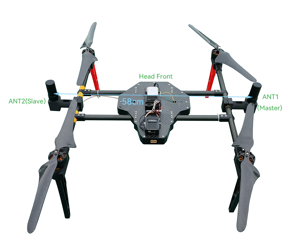
The main antenna is located on the right side of the center of gravity and the slave antenna, 2cm above the center of gravity.
Enable C-RTK2 HP
GPS_TYPE=9(droncan)
EK3_SRC1_YAW =3
CAN_P1_DRIVER=1(CAN1)
GPS_AUTO_CONFIG=2
GPS_MB1_TYPE=1
Antenna offset setting
GPS_MB1_OFF_X=0
GPS_MB1_OFF_Y=0.58
GPS_MB1_OFS_Z=0
Position offset setting
GPS_POS1_X=0.00
GPS_POS1_Y=0.29
GPS_POS1_Z=-0.02
Check heading
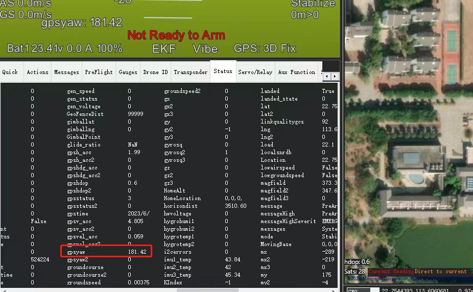
- GPS heading information is in the flight data toolbar of Missin planner > gpsyaw in the status bar.
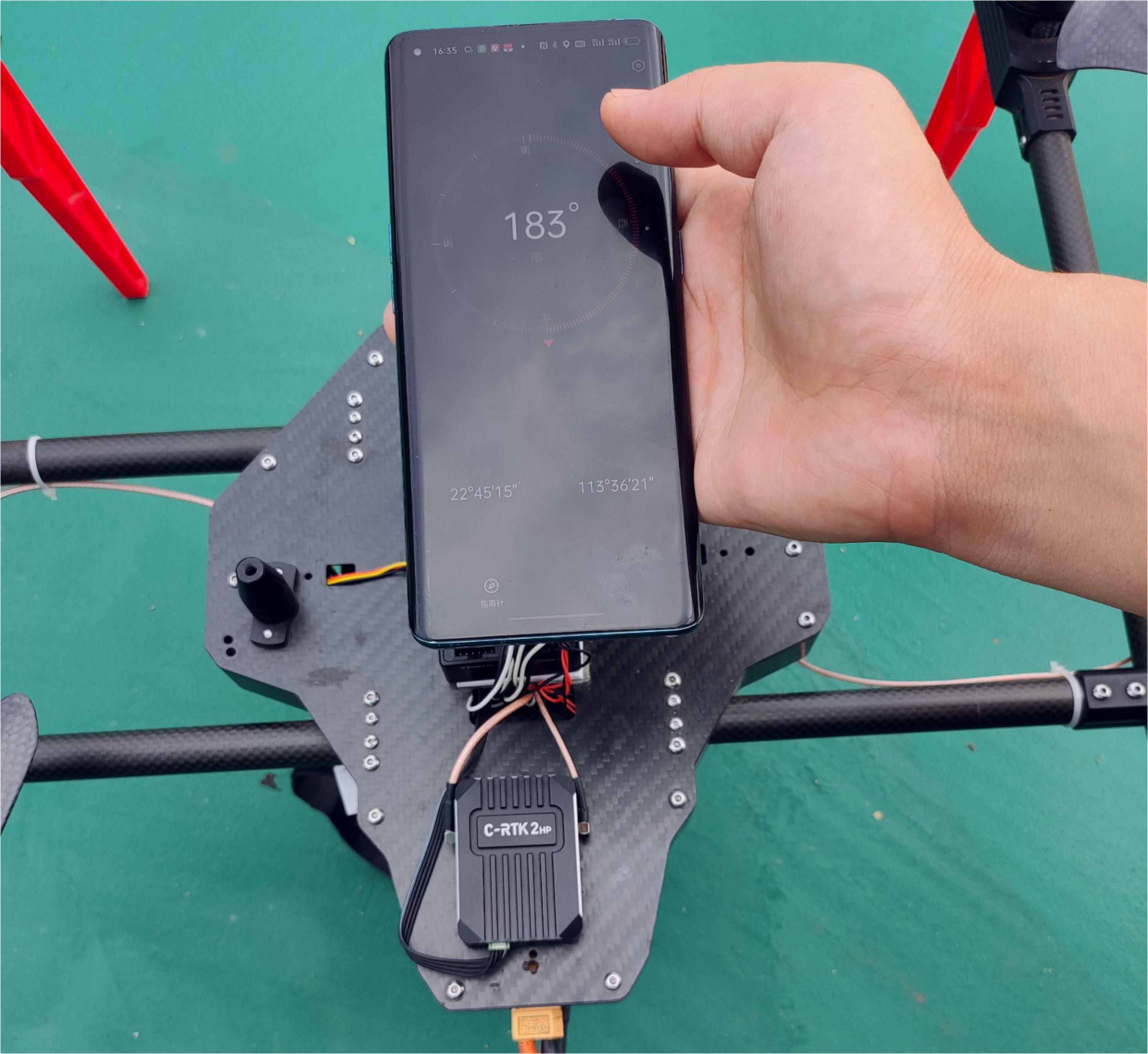
- Check if the gpsyaw value is consistent with the real heading.
- Rotate the airframe to check if the gpsyaw value responds correctly to the rotation.
[!NOTE]
If you can't know the real direction, you can use the phone's built-in compass, etc. as a reference (in the absence of magnetic field interference and not close to the battery)
Purpose of compass
C-RTK2 HP has a built-in RM3100 magnetic compass, which can be used as a safety redundancy (when EK3_SRC1_YAW =3). The compass needs to be calibrated when needed. The installation direction should be consistent with the direction of the aircraft.
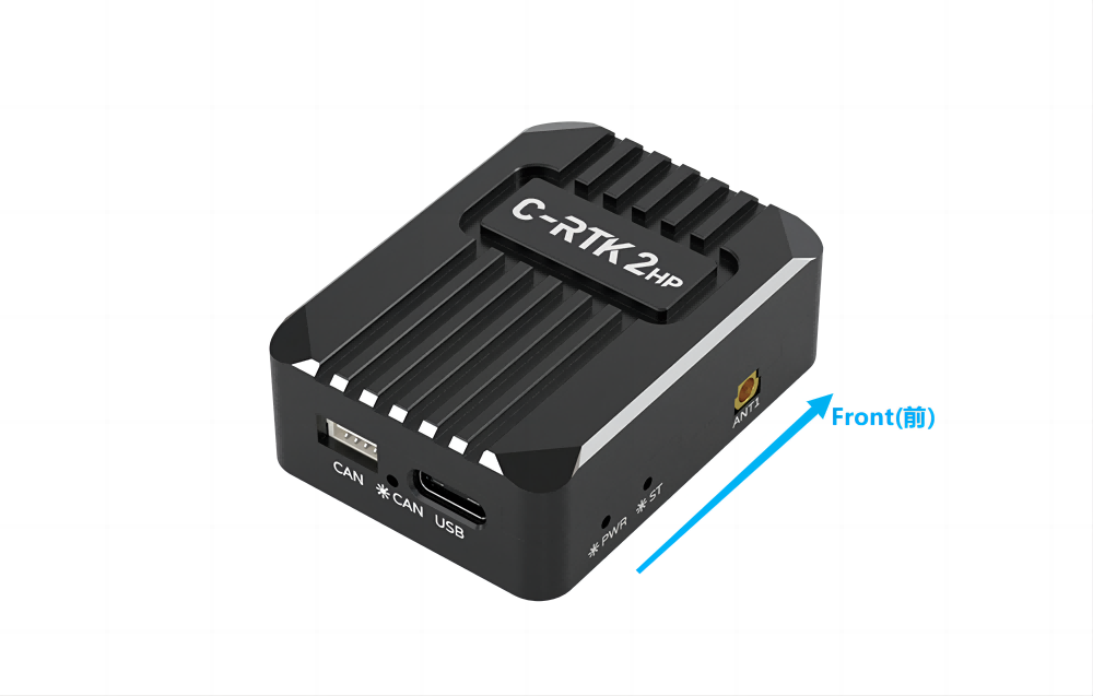
[!NOTE]Compass calibration is not required when the magnetic compass is not in use and can be installed in any orientation
RTK Correction
C-RTK2 HP can be used with C-RTK 9ps base station or Ntrip(CORS )Network RTK base station realizes RTK centimeter-level high-precision positioning, base station configuration: