

Configuration
Factory Configuration
The P9 is pre-configured for point-to-point operation at the factory and normally needs no further setup. Follow the steps below only when changing the network topology or parameters.
Entering Configuration Mode
- Install serial port software, connect the radio to the computer over USB and open the software.
- Set 8 data bits, no parity, 1 stop bit and ASCII for both transmit and receive.
Method 1: hardware buttons
- Set the baud rate to 9600.
- Hold CONFIG and RESET together, release RESET first, then release CONFIG.
Method 2: command
- Set the baud rate to the module's current baud rate (57600 by default) and send:
+++Command Format
Do not append a carriage return to +++. Every other AT command must end with a carriage return, including the last one. Method 2 requires serial port software that can send without a trailing newline.
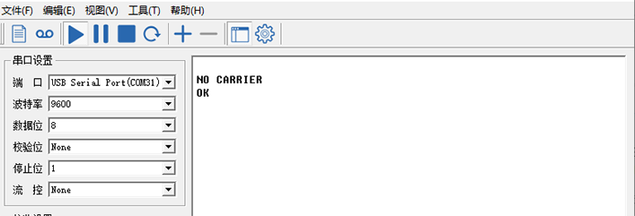
A NO CARRIER ok response confirms AT configuration mode. Each accepted parameter returns ok.
Common AT Commands
- Master: initiates communication and normally serves as the ground station. Its RSSI indicator lights up after receiving data from a slave.
- Slave: collects data and normally serves as the airborne unit. Its RSSI indicator stays on once linked to the master.
- Repeater: an intermediate node that extends the range between master and slave.
| Command | Function | Values | Notes |
|---|---|---|---|
+++ | Enter AT configuration mode | - | No carriage return |
ATA | Exit configuration mode, enter data mode | - | - |
AT&W | Save parameters | - | Send after configuration |
AT&V | Query module parameters | - | Returns current settings and firmware information |
ATSxxx? | Query the current value of a parameter | - | - |
ATSxxx=x | Set a parameter value | - | - |
ATSxxx /? | Query the description of a parameter | - | - |
AT&F10 | Point-to-point master defaults | - | Baud rate becomes 9600 |
AT&F11 | Point-to-point slave defaults | - | Baud rate becomes 9600 |
AT&F12 | Point-to-point repeater defaults | - | Baud rate becomes 9600 |
AT&F7 | Point-to-multipoint master defaults | - | Baud rate becomes 9600 |
AT&F8 | Point-to-multipoint slave defaults | - | Baud rate becomes 9600 |
AT&F9 | Point-to-multipoint repeater defaults | - | Baud rate becomes 9600 |
ATS133 | Communication mode | 0: point-to-multipoint 1: point-to-point | Mode of the communication network |
ATS101 | Working mode | 0: master 1: repeater 2: slave | Role of this module in the network |
ATS102 | Serial baud rate | 0: 230400 1: 115200 2: 57600 3: 38400 4: 28800 5: 19200 6: 14400 7: 9600 8: 7200 9: 4800 10: 3600 11: 2400 12: 1200 13: 600 14: 300 | All devices in the network must match |
ATS103 | Air data rate | 0: 172800 1: 230400 2: 276480 3: 57600 4: 115200 | Higher rates increase bandwidth but reduce sensitivity, range and stability |
ATS108 | Transmit power (mW) | 20: 100 21: 125 22: 160 23: 200 24: 250 25: 320 26: 400 27: 500 28: 630 29: 900 30: 1000 | Higher power extends the range |
ATS104 | Network IP | 1 ~ 4294967295 | All devices in the network must match |
ATS105 | Local device address | 1 ~ 65535 | Each device in the network needs a unique address |
ATS140 | Target device address | 1 ~ 65535; 65535 broadcasts | Must match the peer's ATS105 |
ATS141 | Repeater enable | 0: disabled 1: enabled | Effective on the master only |
ATS118 | Address to synchronize | 1: default 65535: broadcast | - |
Point-to-Point Communication
Copy the parameters below into the serial port software, append a carriage return and send. Each line returns ok when accepted.
Master (ground station)
AT&F10
ATS102=2
ATS104=725527
AT&W
AT&V
Slave (airborne unit)
AT&F11
ATS102=2
ATS104=725527
AT&W
Point-to-Point with a Repeater
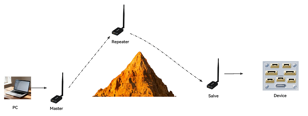
Master (ground station)
AT&F10
ATS102=2
ATS104=725527
ATS141=1
AT&W
Slave (airborne unit)
AT&F11
ATS102=2
ATS104=725527
ATS118=3
AT&W
Repeater
AT&F12
ATS102=2
ATS104=725527
AT&W
Repeater Throughput
Adding a repeater halves network throughput. With ATS118=3 on the slave, the link is established only through the repeater. Set it to 65535 to allow a direct link to the master when available, with repeater forwarding only at long range.
Point-to-Multipoint Communication
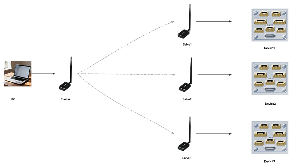
Master
AT&F7
ATS102=0
ATS103=2
ATS104=725527
ATS108=30
ATS105=1
ATS140=65535
AT&W
Slave 1
AT&F8
ATS102=0
ATS103=2
ATS104=725527
ATS108=30
ATS105=2
ATS140=1
AT&W
Slave 2
AT&F8
ATS102=0
ATS103=2
ATS104=725527
ATS108=30
ATS105=3
ATS140=1
AT&W
Slave 3
AT&F8
ATS102=0
ATS103=2
ATS104=725527
ATS108=30
ATS105=4
ATS140=1
AT&W
Slave 4
AT&F8
ATS102=0
ATS103=2
ATS104=725527
ATS108=30
ATS105=5
ATS140=1
AT&W
Adding Slaves
For each additional slave, set ATS105 to a unique value and keep ATS140 at the master address 1. When connecting to an ArduPilot controller, set the serial baud rate to 230400 (SERIALx_BAUD=230) and give each device a unique SYSID_THISMAV.