

C-RTK3 G5 Centimeter-Level Positioning and Heading Module
The C-RTK3 G5 is a new-generation centimeter-level positioning and heading module launched by CUAV. It integrates the high-performance STM32H5 processor and GNSS+ technology suite, and supports the CAN FD bus.
It reliably handles complex application scenarios such as radio interference, electromagnetic interference, positioning spoofing, high vibration, and high maneuverability. It effectively expands the application boundaries of intelligent devices and provides core support for stable, safe and accurate positioning and heading. It is widely applicable to satellite positioning devices including vehicle navigation systems, robots, drones and unmanned ground vehicles.
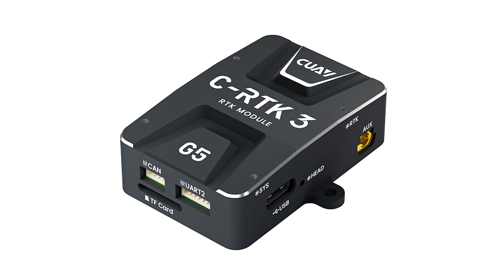
Product Features
- RTK positioning accuracy: 0.6 cm + 0.5 ppm
- Dual-antenna heading, no compass calibration required
- Multi-constellation and multi-frequency positioning & heading
- High-performance STM32H5 processor
- CAN FD + 20 Hz high refresh rate
- Interference detection and alarm
- All-round anti-interference and anti-spoofing capability
- LOCK+ fusion algorithm for stable signal tracking under high vibration and impact
- 2-channel EVENT with configurable PPS output
Electrical & Hardware Specifications
| C-RTK3 G5 | Specifications |
|---|---|
| Processor | STM32H5 Arm® Cortex®-M33, 250 MHz |
| GNSS Hardware Channels | 789 |
| Supported Constellations & Frequency Bands | GPS: L1C/A, L2C, L2PY, L5, L1C GLONASS: L1CA, L2CA, L2P, L3 CDMA BDS: B1I, B1C, B2a, B2I, B3I, B2b Galileo: E1, E5a, E5b, E6 QZSS: L1C/A, L1C/B, L2C, L5, L6 |
| Antenna Configuration | Dual-antenna; single/dual-antenna working mode configurable |
| Raw Data Output | Supported / TF card logging available |
| Positioning Accuracy | Single Point: Horizontal 1.2 m, Vertical 1.9 m DGNSS Aided: Horizontal 0.4 m, Vertical 0.7 m RTK: Horizontal 0.6 cm + 0.5 ppm, Vertical 1 cm + 1 ppm |
| Velocity Accuracy | 3 cm/s |
| Heading Accuracy | 0.15° @ 1 m antenna baseline 0.03° @ 5 m antenna baseline |
| Max Update Rate | 20 Hz |
| RTK Initialization Time | 7 s (Baseline < 40 km) |
| Timing Performance | PPS Resolution: 1.4 ns Event Accuracy: < 3 ns Cold Start: < 35 s (No ephemeris / No approximate position) Hot Start: < 10 s (With ephemeris & approximate position) Re-acquisition Time: 1 s |
| Tracking & Acquisition Threshold | Tracking: 20 dB/Hz Acquisition: 30 dB/Hz |
| Onboard Compass | RM3100 |
| Communication Protocols | DroneCAN / SBF / NMEA-0183 / RTCM |
| Communication Baud Rate | 1 Mbit/s (CAN) 8 Mbit/s (CAN FD) |
| Firmware Upgrade | Supported |
| Default Firmware | C-RTK3 M4C |
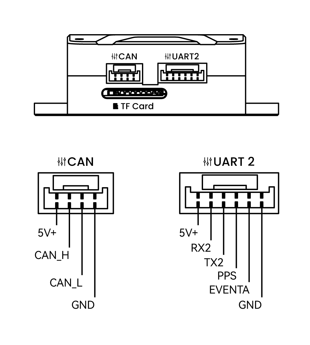
| Interfaces | 1 × CAN (GH1.25 4P) 1 × UART (GH1.25 6P) 1 × USB Type-C 2 × Antenna Port (BWMCX-KEF) 1 × TF Card Slot |
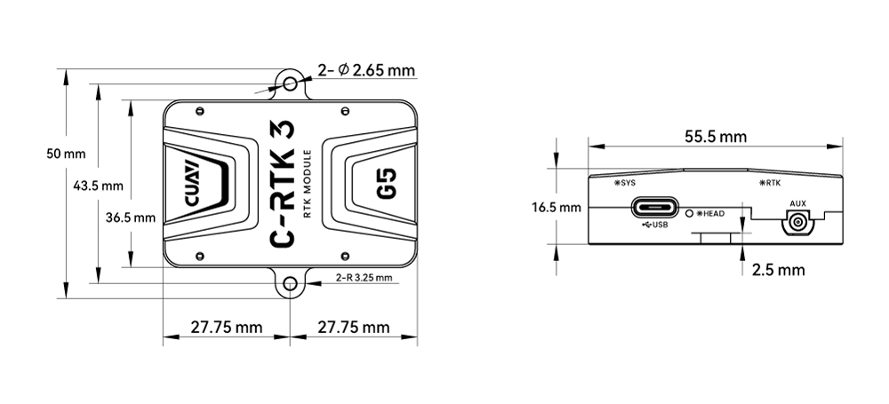
| Dimensions | 55.5 × 50 × 16.5 mm (Including mounting holes) |
| Weight | 43.5 g (Excluding antenna and cable) |
| Operating Temperature | -10 ℃ ~ +80 ℃ |
CRA-602 Antenna Specifications
| CRA-602 Antenna | Specifications |
|---|---|
| Coverage Angle | 360° |
| Polarization | Right-Hand Circular Polarization |
| LNA Gain | 38±2 dB |
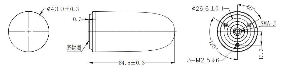
| Connector Type | SMA-J |
| Dimensions | Φ40 × 84.5 mm |
| Weight | 36 g |
Dimensions
C-RTK3 G5 Dimension Drawing
CRA-602 Antenna Dimension Drawing
Purchase
Pin Definition
LED Status Indicators
NOTE
The silkscreen markings are located beside the LED indicators; the RTK status LED is inactive in base station mode.
| Indicator | Icon | Blink Pattern | Description |
|---|---|---|---|
| PWR |  | Solid on | The module is powered normally; the red LED stays on |
| SYS |  | Slow blink (1 Hz) | The module is powered normally; the yellow LED blinks once per second |
| SYS |  | Fast blink | The yellow LED blinks fast while the firmware is being upgraded |
| SYS |  | Solid on | The yellow LED stays on when the module reports an error |
| PPS |  | Solid on → off | At power-on the yellow LED turns on and then goes off after a few seconds |
| PPS | | Blink (1 Hz) | Once the module obtains a position fix, the yellow LED blinks once per second by default |
| CAN |  | Fast blink | After the module is connected to the flight controller over CAN, the green LED blinks fast; the faster it blinks, the more CAN messages are received |
| HEAD |  | Off | The module is powered but no heading message is available; the green LED stays off |
| HEAD |  | Solid on | The module is powered and heading messages are available; the green LED stays on |
| RTK |  | Off | No RTK fix; the blue LED stays off |
| RTK |  | Blink | RTK Float; the blue LED blinks |
| RTK |  | Solid on | RTK Fixed; the blue LED stays on |
C‑RTK3 G5 System Parameters
NOTE
The following are internal configuration parameters for the C‑RTK3 G5; modification is generally unnecessary.
| Parameter | Range / Options | Default | Description |
|---|---|---|---|
CAN1_FD_BITRATE | 1–8 (Mbps) | 4 | CAN1 FD data segment bitrate |
CAN1_FD_EN_MODE | 0~2 | 2 | CAN FD enable: 0 = disable (Classic CAN); 1 = force enable CAN FD; 2 = auto (system selects based on bus load and handshake) |
CAN_NODE_ID | 0~125 | 0 | CAN node ID; 0 = auto‑assigned by controller; set to a unique non‑zero value if conflicts occur |
CAN_R | True/False | False | Enable CAN 120Ω termination resistor; True = enable; recommended for multi‑node buses |
FLASH_BOOTLOADER | True/False | False | Update bootloader; automatically resets to False after completion |
GNSS_CFG_MODE | 0/1 | 1 | Receiver configuration: 0 = bypass; 1 = auto-configured by the main controller |
GNSS_DYN_MODEL | 0–13 | 10 | Dynamic model: 0=Base Station,1=Quasi‑static,2=Robot,3=Pedestrian,4=Automotive,5=Motorcycle, 6=Racing,7=Heavy Machinery,8=Marine,9/10/11=UAV,12=Wearable,13=Unconstrained |
GNSS_EN_ATTITUDE | 0/1 | 1 | 0 = single‑antenna; 1 = dual‑antenna heading |
GNSS_ITFM_SEND | — | 0 | Send interference/spoofing detection data via CAN |
GNSS_MODE | 0–65535 (bitmask) | 109 | Satellite constellation: Bit0=GPS, Bit1=SBAS, Bit2=Galileo, Bit3=BeiDou, Bit4=IMES, Bit5=QZSS, Bit6=GLONASS, Bit7=NavIC |
GNSS_RATE_MS | 50/100/200/500 (ms) | 100 | GNSS output period: 100ms=10Hz, 50ms=20Hz |
GNSS_RTK_MSM_VER | bitmask | 16 | RTCM MSM version. Default 16 (0b00010000) = MSM4; 128 (0b10000000) = MSM7; 144 (0b10010000) outputs both MSM4 and MSM7 (generally not recommended) |
GNSS_UART2_BAUD | 1200~4000000 | 460800 | UART2 baud rate |
GNSS_UART2_PROT | 0–65535 (bitmask) | 10 | UART2 protocol: Bit0=UBLOX, Bit1=NMEA, Bit2=RTCM, Bit3=SBF; Common: 2=NMEA, 8=SBF, 10=NMEA+SBF |
GPS_MB_ONLY_PORT | — | 0 | Reserved for APM compatibility, unused |
GPS_TYPE | — | 1 | Fixed system configuration, not applicable |
SEP_ELE_MASK | -90~90 (°) | 10 | Satellite elevation mask angle (angle from local horizontal to satellite); satellites below this angle excluded from PVT; recommend 15~20° in urban/mountain/interference environments |
SEP_PPP_ENABLE | 0/1 | 1 | Enable PPP positioning |
SEP_PPS_DUTY | 1–99 (%) | 5 | PPS duty cycle (max pulse width: 1000ms) |
SEP_PPS_POL | 0/1 | 0 | PPS polarity: 0=Low→High;1=High→Low |
SEP_PPS_PRD | 0–21 | 15 | PPS output period: 0=Off;1=10MHz;2=1MHz;3=100KHz;4=10KHz;5=5KHz;6=2KHz;7=1KHz;8=100Hz;9=50Hz;10=20Hz;11=10Hz;12=5Hz;13=4Hz;14=2Hz;15=1Hz;16=2S;17=4S;18=5S;19=10S;20=30S;21=60S |
SEP_RTCM_RATE | 50/100/200/500 (ms) | 500 | RTCM data output rate (default value corrected to 500) |
SEP_SL | 0–200 (s) | 20 | Carrier‑smoothed pseudorange duration |