
C-RTK3 G5 User Guide
This chapter applies to the scenario of using the C-RTK3 G5 with ArduPilot vehicles.
NOTE
ArduPilot 4.4.0 and later versions support the C-RTK3 G5.
Flight Controller Parameter Configuration (CAN Connection, Recommended)
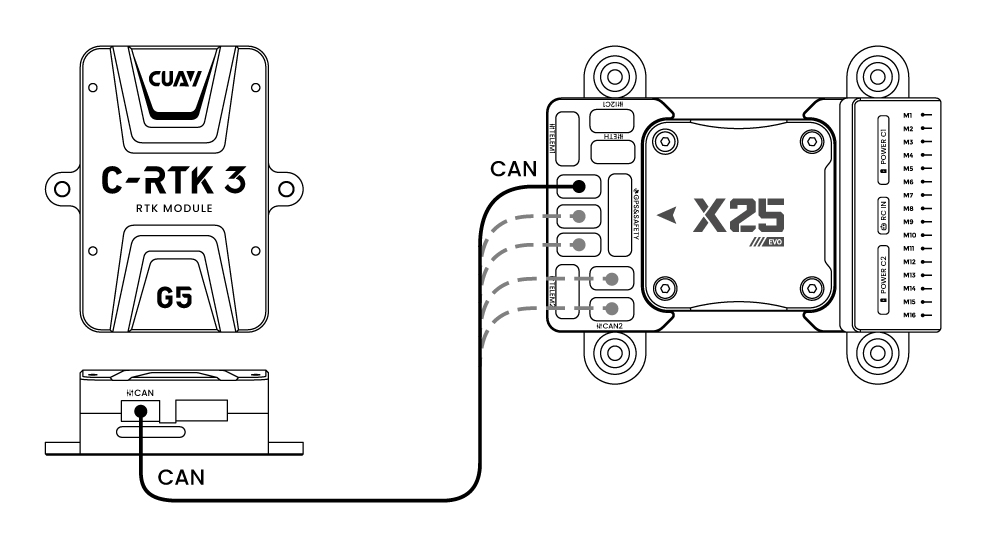
- Take out the CAN cable from the accessory package, connect the flight controller to the CAN port of the C-RTK3 G5; install the antennas for the C-RTK3 G5, and keep the distance between the two antennas more than 20 cm.
- Connect the flight controller to the ground station (such as Mission Planner / LGC) via USB.
- Enter the Full Parameter List, input parameter names in the search bar and set the following parameters.
// Mission Planner path: Configuration/Tuning → Full Parameter List → Search bar on the right
| Parameter | Value | Remark |
|---|---|---|
GPS1_TYPE | 9 | DroneCAN: 9; UART: 26 |
CAN_P1_DRIVER | 1 | Enable CAN1 driver |
GPS_AUTO_CONFIG | 2 | Auto configure DroneCAN GPS |
EK3_SRC1_YAW | 2 or 3 | 2: GPS; 3: GPS priority with compass backup |
GPS1_MB_TYPE | 1 | Master-to-slave antenna offset configuration |
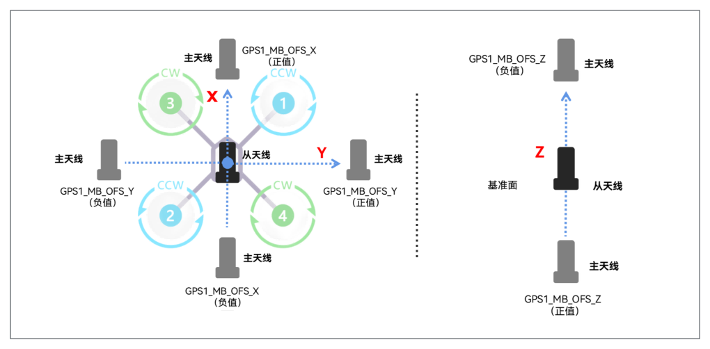
GPS1_MB_OFS_X | Value (m); set according to installation | X-axis offset of master antenna, positive forward of slave antenna |
GPS1_MB_OFS_Y | Value (m); set according to installation | Y-axis offset of master antenna, positive right of slave antenna |
GPS1_MB_OFS_Z | Value (m); set according to installation | Z-axis offset of master antenna, positive below slave antenna |
GPS1_POS_X | Value (m); set according to installation | X-axis offset relative to center of gravity, positive forward |
GPS1_POS_Y | Value (m); set according to installation | Y-axis offset relative to center of gravity, positive right |
GPS1_POS_Z | Value (m); set according to installation | Z-axis offset relative to center of gravity, positive below CG |
Master-Slave Antenna Offset Diagram
NOTE
The MAIN port is the master antenna and the AUX port is the slave antenna.
For controllers running older firmware below ArduPilot 4.6 (exclusive):
| Parameter | Value | Remark |
|---|---|---|
GPS_TYPE | 9 | DroneCAN: 9; UART: 26 |
CAN_P1_DRIVER | 1 | Enable CAN1 driver |
GPS_AUTO_CONFIG | 2 | Auto configure DroneCAN GPS |
EK3_SRC1_YAW | 2 or 3 | 2: GPS; 3: GPS priority with compass backup |
GPS_MB1_TYPE | 1 | Master-to-slave antenna offset configuration |
GPS_MB1_OFS_X | Value (m); set according to installation | X-axis offset of master antenna, positive forward of slave antenna |
GPS_MB1_OFS_Y | Value (m); set according to installation | Y-axis offset of master antenna, positive right of slave antenna |
GPS_MB1_OFS_Z | Value (m); set according to installation | Z-axis offset of master antenna, positive below slave antenna |
GPS_POS1_X | Value (m); set according to installation | X-axis offset relative to center of gravity, positive forward |
GPS_POS1_Y | Value (m); set according to installation | Y-axis offset relative to center of gravity, positive right |
GPS_POS1_Z | Value (m); set according to installation | Z-axis offset relative to center of gravity, positive below CG |
Heading Verification
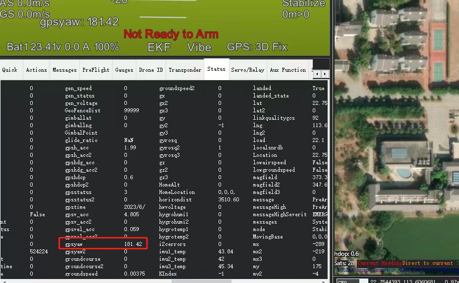
- GPS heading data is displayed as gpsyaw in the status bar of Mission Planner flight data toolbar.
- Check whether the gpsyaw value is consistent with the actual heading.
- Rotate the airframe and verify if the gpsyaw value responds correctly to rotation.
NOTE
If you cannot confirm the actual direction, you may use the built-in compass of a mobile phone for reference. Keep away from batteries to avoid magnetic interference.
UART Connection Parameter Configuration
NOTE
ArduPilot 4.4.0 and later versions support the C-RTK3 G5.
| Parameter | Value | Remark |
|---|---|---|
GPS1_TYPE | 26 | DroneCAN: 9; UART: 26 |
GPS_AUTO_CONFIG | 1 | Auto configure serial GPS |
EK3_SRC1_YAW | 2 or 3 | 2: GPS; 3: GPS priority with compass backup |
GPS1_MB_TYPE | 1 | Master-to-slave antenna offset configuration |
GPS1_MB_OFS_X | Value (m); set according to installation | X-axis offset of master antenna, positive forward of slave antenna |
GPS1_MB_OFS_Y | Value (m); set according to installation | Y-axis offset of master antenna, positive right of slave antenna |
GPS1_MB_OFS_Z | Value (m); set according to installation | Z-axis offset of master antenna, positive below slave antenna |
GPS1_POS_X | Value (m); set according to installation | X-axis offset relative to center of gravity, positive forward |
GPS1_POS_Y | Value (m); set according to installation | Y-axis offset relative to center of gravity, positive right |
GPS1_POS_Z | Value (m); set according to installation | Z-axis offset relative to center of gravity, positive below CG |
SERIAL3_PROTOCOL | -1 | Disable Serial3 if no GPS is connected to GPS&Safety port; GPS2/UART4 will be recognized as GPS1 |
SERIAL4_PROTOCOL | 5 | Set Serial4 as GPS port, generally no modification required |
SERIAL4_BAUD | 460800 | Set Serial4 baud rate to 460800 |
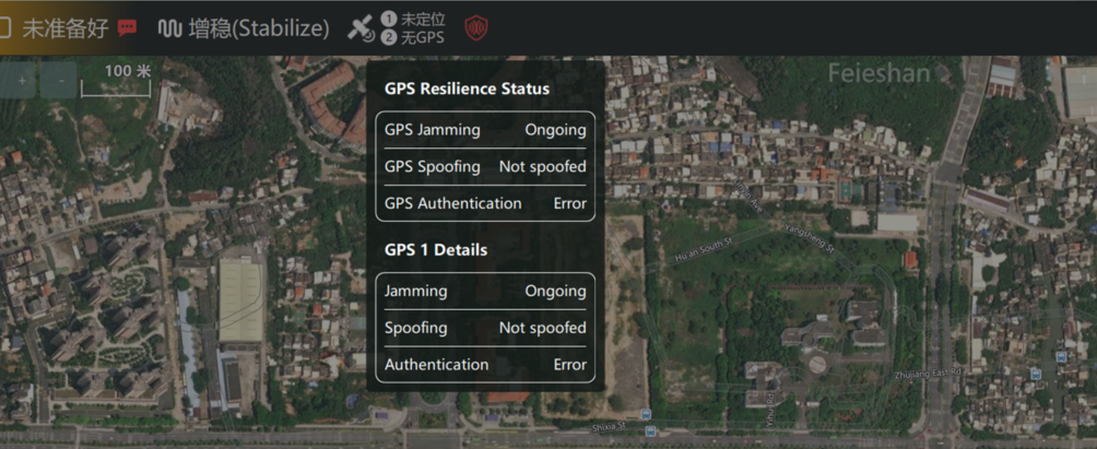
Interference Status Display
NOTE
The C-RTK3 G5 supports interference status display, which requires compatible flight controller firmware and ground station support. Please contact CUAV technical support if needed.