

C-RTK2 Quick start
This section introduces how to quickly configure and use C-RTK 2.
Build an aerial survey system
According to your different needs, you need to prepare the following equipment first
Only use PPK
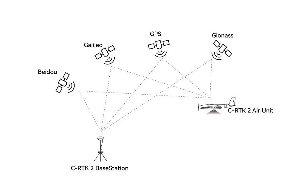
- PPK base station/Ntrip account *1
- C-RTK 2 *1
- Mapping camera *1
- Drone *1
PPK+RTK
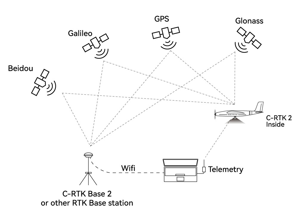
- PPK base station/Ntrip account *1
- C-RTK 2 *1
- Mapping camera *1
- Drone *1
- Data link *1
- Computer *1
NOTE
C-RTK 2 is used as an RTK base station and rover station, as well as a PPK rover station, It is not recommended to be used as a PPK base station.
Hardware connection
According to different camera types, there are different connection methods
Five-lens mapping camera/DIY method
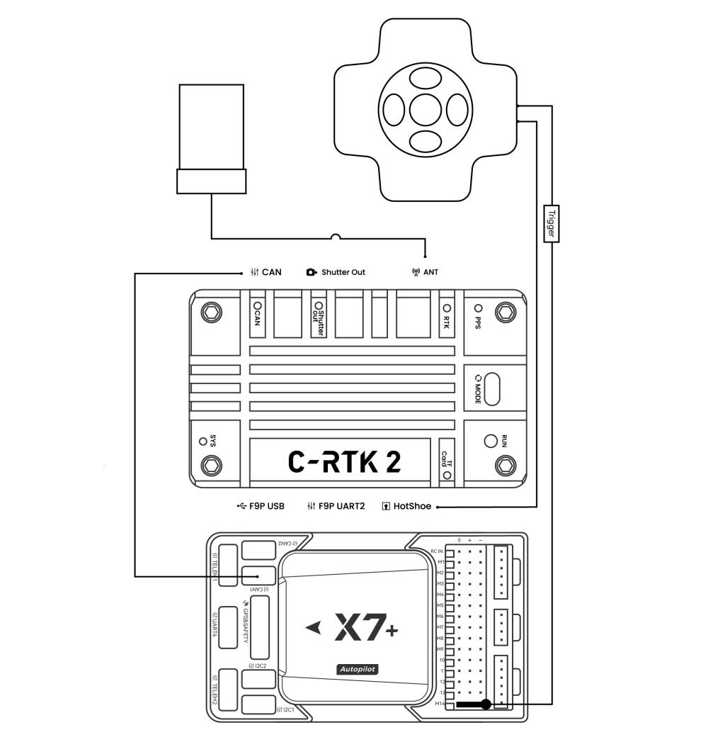
- Use CAN cable to connect flight controller and C-RTK2 (communication and power supply)
- Use the hot shoe cable to connect to the hot shoe cable of the five-lens camera
- The shutter trigger pin of the flight control is connected to the five-lens camera shutter cable
Canon/Sony cameras and other cameras with hotshoes
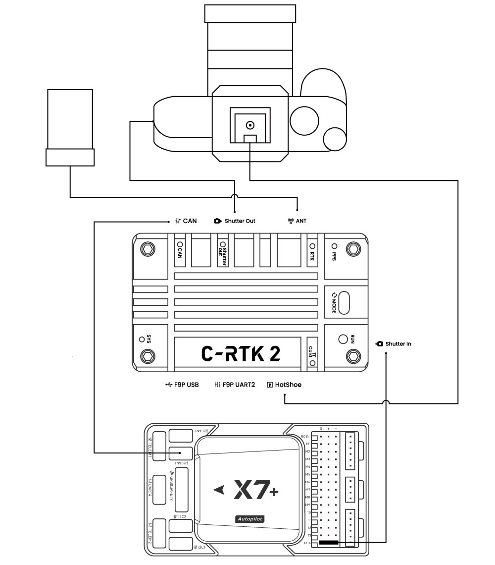
- Use CAN cable to connect flight controller and C-RTK2 (communication and power supply)
- Use the hotshoe cable to connect to the hotshoe PCB and C-RTK Hotshoe interface, and insert the PCB into the camera hot shoe interface
- The shutter trigger pin of the flight control is connected to the Shutter in interface
- C-RTK2 Shutter out is connected to the camera shutter interface
NOTE
The above is the recommended method of use. You can also use it with a camera without hot shoe feedback and use the shutter trigger to record the POS; but you may need to tolerate the accuracy error caused by the delay.
Camera without hot shoe (shutter trigger recording pos)
NOTE
For some special cameras without hot shoe feedback, C-RTK supports the use of shutter trigger to record POS; but due to various reasons, there is an error (delay) between the camera and POS recording time; it may affect the accuracy of aerial survey; when using this method The C-RTK 2 parameter CAM_FEEDBACK_TYPE needs to be set to 0.
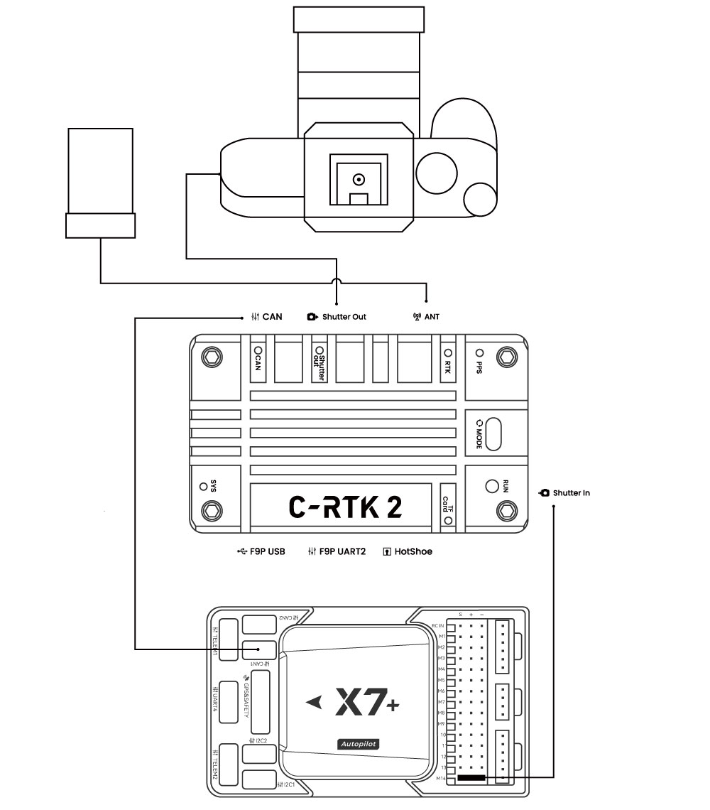
- Use the CAN cable to connect the flight controller and the CAN (communication and power supply) of the C-RTK2.
- The shutter trigger pin of the flight controller is connected to the Shutter in interface
- C-RTK2 Shutter out is connected to the camera shutter port
Install to drone
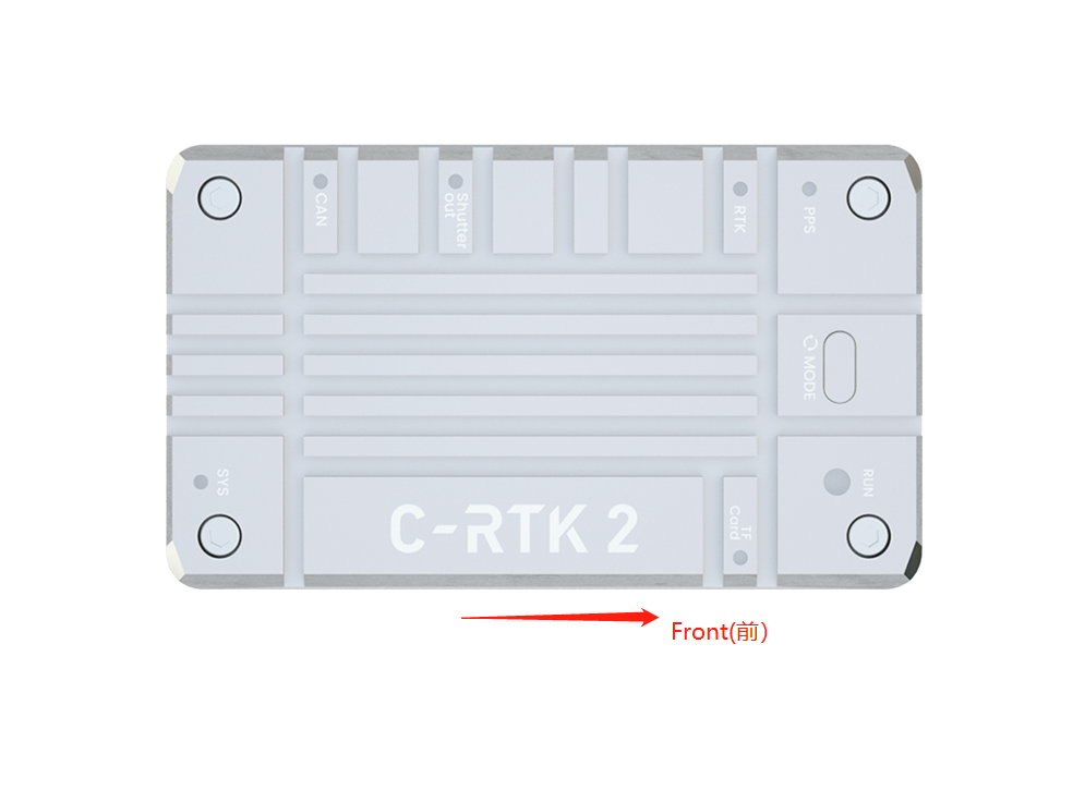
NOTE
The direction of the device should be consistent with the direction of the aircraft; otherwise, you may need to configure additional flight control parameters
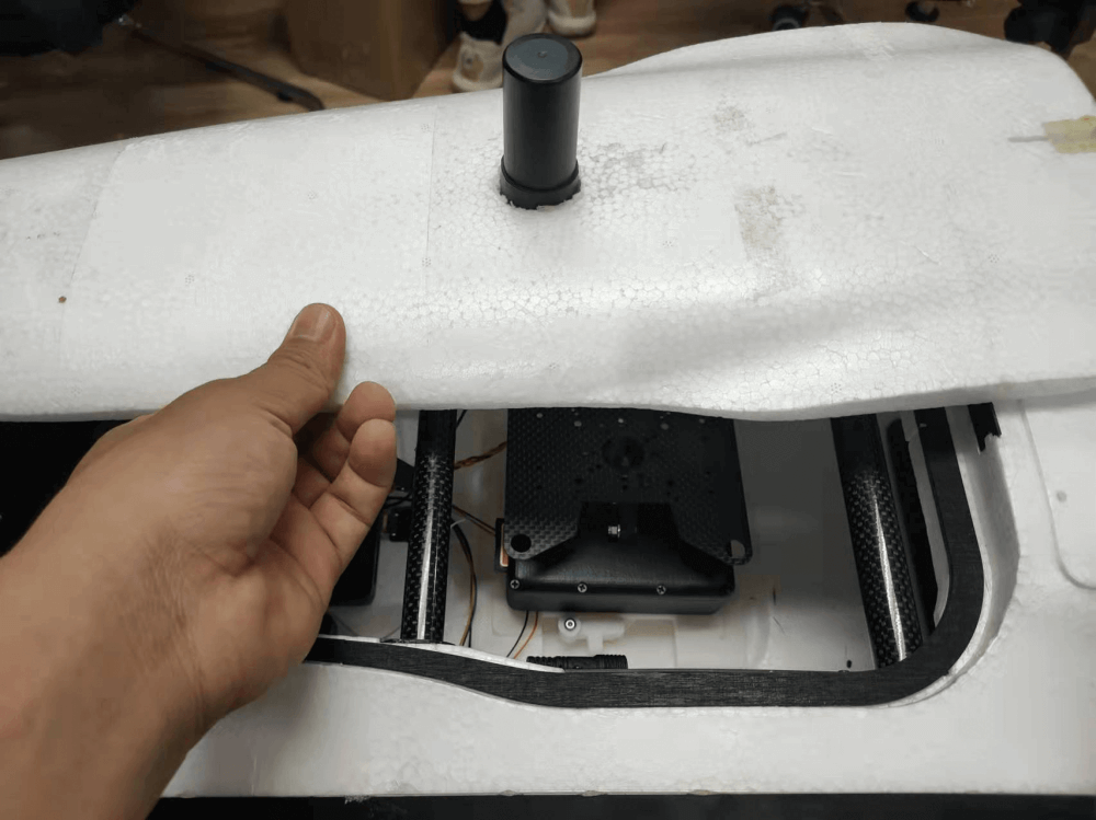
NOTE
It is recommended to install the C-RTK2 antenna directly above the camera to avoid configuring the antenna offset.
Set flight control parameters
Depending on the flight controller firmware, the set parameters are different. The following is the setting guide for ArduPilot/PX4 firmware. If you use other flight controllers, please refer to the relevant controller shutter setting guide; the following configuration uses common relay/level shutter trigger as an example; also supports PWM shutter trigger.
ArduPilot
NOTE
The flight control parameters are set in MissionPlanner > Configuration > All parameter table/parameter tree. After modification, please click the write button on the right side and restart the flight control.
Enable UAVCAN
NOTE
The following settings are to enable UAVCAN to provide RTK/navigation data for the flight controller; if you only use C-RTK 2 as a PPK, you do not need to perform this operation.
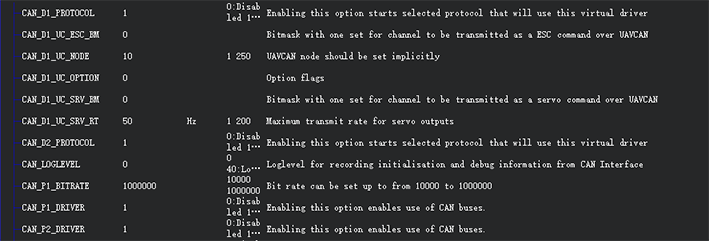
CAN_D1_PROTOCOLset to 1.CAN_P1_DRIVERset to 1 (Enable CAN1).CAN_D2_PROTOCOLset to 1.CAN_P2_DRIVERset to 1 (Enable CAN2).GPS_TYPEorGPS1_TYPEset to 9 (AP4.6.0 and later).
Set the flight control camera shutter output
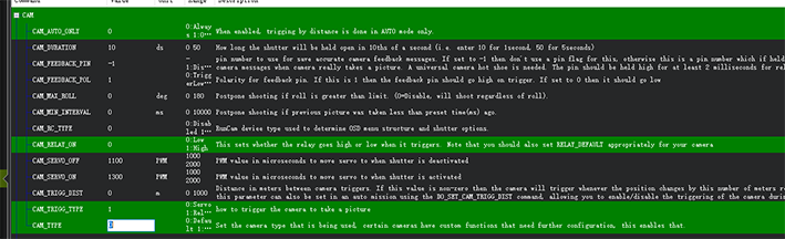
CAM_TRIGG_TYPEset to 1 (0=PWM, 1=relay).CAM_RELAY_ONset to 0 (0=low, 1=high).CAM_MIN_INTERVALset to 0 (The shortest shutter interval time, unit: milliseconds, 1000=1 second).CAM_MAX_ROLLset to 0 (If the tilt exceeds this angle, the time-lapse shooting will not trigger until the angle returns to normal, 0=no limit).CAM_AUTO_ONLYset to 0 (When to on the shutter, 0=anytime, 1=only in AUTO mode).RELAY_PINset to 55 (Relay pin; The flight controller without io should be set to 63).
For AP4.6 and above version firmware
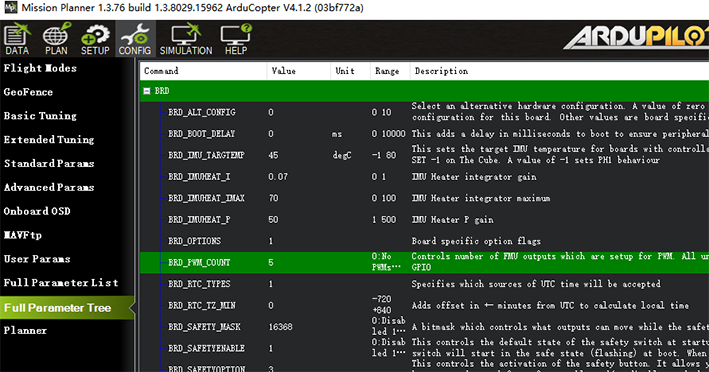
CAM1_TYPEset to 1 (1=PWM, 2=relay).CAM1_RELAY_ONset to 0 (0=low, 1=high).CAM1_MIN_INTERVALset to 0 (The shortest shutter interval time, unit: milliseconds, 1000=1 second).CAM1_MAX_ROLLset to 0 (If the tilt exceeds this angle, the delayed shooting will not be triggered until the angle returns to normal, 0=no limit).CAM_AUTO_ONLYset to 0 (when the shutter can be triggered, 0=any time, 1=only in AUTO mode).RELAY_PINset to 55 (Relay pin; The flight controller without io should be set to 63).CAM1_FEEDBACK_PINset to 54 (Relay pin; The flight controller without io should be set to 62).CAM1_FEEDBAK_POLset to 1 (0=low, 1=high).
Test shutter trigger
- Use the remote control to control the shutter:
RC?_OPTION=9 (?=Remote control channel, for example,RC7_OPTIONset to 9, then the remote control channel 7 is dialed to the high position to take pictures). - Ground station instructions:
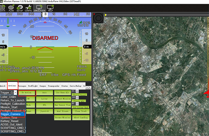
In the action bar of the flight data of the ground station, select Trigger_camera and click to execute the action to trigger the camera.
PX4
NOTE
The flight control parameters are set in QGroundcontrol > parameters. After modification, please click the ok button on the right and restart the flight control.
Enable UAVCAN
NOTE
The following settings are to enable UAVCAN to provide RTK/navigation data for the flight controller; if you only use C-RTK 2 as a PPK, you do not need to perform this operation.
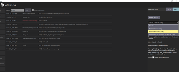
UAVCAN_ENABLEset to Sensors Automatic Config(Automatic configuration of node ID).
Set the flight control camera shutter output
TRIG_MODEset to 1 (Trigger mode).TRIG_INTERFACEset to 1 (relay).TRIG_PINS(Shutter trigger pin, If triggering on AUX5 and AUX6, it should be set to 56.).TRIG_ACT_TIMEset to 200 (Camera output duration, unit ms).TRIG_POLARITYset to 0 (0=low,1=high).
C-RTK2 parameters
NOTE
It is not necessary to configure C-RTK2 when using the relay to control the camera shutter; when the camera cannot be controlled to take pictures, please check the following parameters.
UAV_ENABLEset to 1 (Enable shutter input).UAV_MODEset to 0 (Relay input mode).UAV_POLARITYset to 0 (The trigger polarity of the shutter input; related to the flight control TRIG_POLARITY/CAM_RELAY_ON).CAM_DURATIONset to 10 (Duration that shutter is held open).CAM_POLARITYset to 0 (Default:0).CAM_FEEDBACK_TYPEset to 1 (Hotshoe is 1, shutter is 0).CAM_STset to 0 (Shutter compensation time, set to 0 when using the hotshoe).