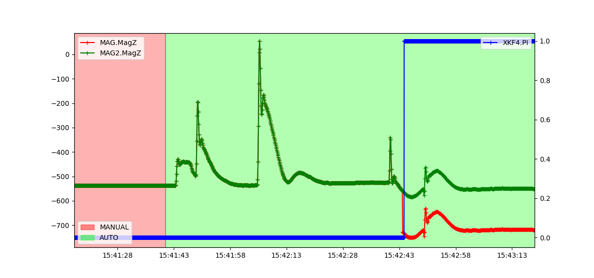

Analysing EKF Lane Switching
EKF3 runs several independent filter lanes at once across multiple IMUs, each lane bound to its own IMU and sensor sources. When the primary lane's filter error rises — a bad sensor, too much noise, drifting data — EKF3 switches lanes automatically, handing attitude, position and velocity output to a standby lane with lower error. That is what makes the flight fault-tolerant.
What to do when a switch happens
Lane switching is the core active-redundancy mechanism on multi-IMU, multi-sensor hardware. The aircraft may wobble slightly during the switch. Do not respond by lowering the error threshold or turning lane switching off — the controller would then fly on a bad attitude estimate, which is a fast route to loss of control. Work out the root cause from the flight log instead.
How the lanes run in parallel
There are as many lanes as there are IMUs, and they all run in the background:
- Active lane: publishes the navigation data and takes part in closed-loop control
- Standby lane: computes in parallel, takes no part in control, exists purely as redundancy
In normal flight the system stays on the best lane; when the active lane's error exceeds the threshold, it switches to the better one.
What triggers a switch
EKF3 uses each lane's combined fusion error score (NKFx.Err), compared against EK3_ERR_THRESH:
- Active lane error above the threshold, with a standby lane lower → switch
- Lower error means a more stable sensor fusion and more trustworthy data
- A lower threshold switches more readily; a higher one makes it more conservative
Finding the switch cause in a log
- Load the flight log into a log analysis tool (Mission Planner, for example)
- Compare
XKF4.PIagainst the sensor data.PIis the EKF3 switch flag: going from 0 to 1 means control moved from the primary lane to lane 2.
Example: an airspeed sensor causing the switch
This aircraft has two airspeed sensors, so two airspeed data streams. At first there is no pressure difference between them and the EKF is happy. As speed builds, airspeed 1 still reports no change; comparing across sensors, the system decides airspeed 1 is faulty and airspeed 2 is trustworthy, and EKF3 switches to the standby lane — PI flips. Later, as speed drops, airspeed 2 fails in the same way and the lane switches again. 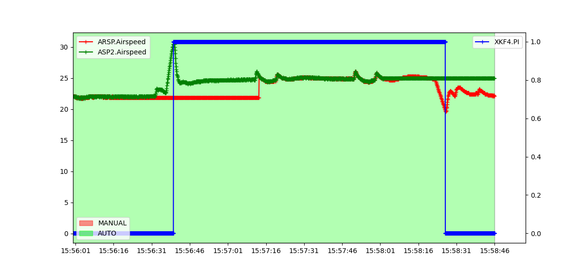
Example: a barometer causing the switch
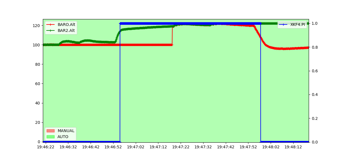
Here two barometers are enabled, so there are two pressure streams. After the aircraft climbs, the primary lane's barometer fails to show the pressure change, so EKF switches lanes.
Example: GPS causing the switch
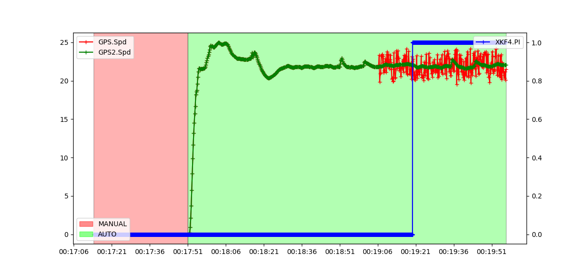
Two GPS units are enabled, so there are two position streams. The primary lane's GPS is given random velocity noise of ±2 m across all three axes, while the second GPS tracks the real velocity. The primary lane's error climbs, and once it passes the threshold the lane switches.
Example: a compass causing the switch
Two compasses here. The Z axis of one compass jumps, while the EKF estimate and the second magnetometer keep tracking correctly. The primary lane's error climbs and, once past the threshold, EKF switches lanes.