

Wheel Encoder Setup
Rover firmware supports up to two AB-phase wheel encoders, which sharpen position estimation and matter most when there is no GPS. An encoder mounts on the motor shaft or the wheel axle, one per side of the vehicle.
Wiring and setup
Phases A and B each take an output. Before wiring, those two outputs have to be switched from servo output to plain IO.
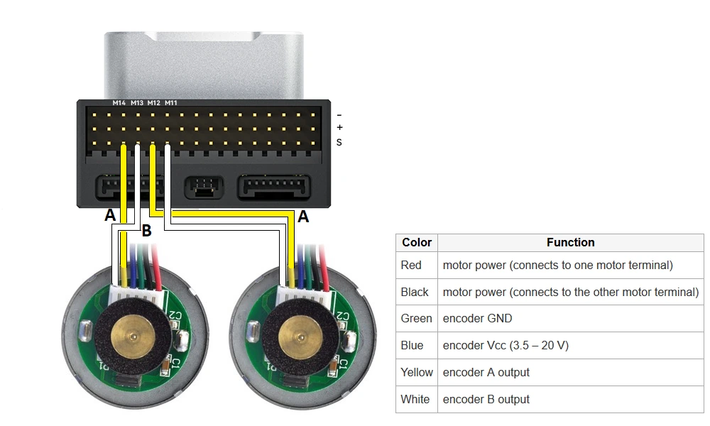
▲ A and B each take an output; yellow is phase A, white is phase B, green is GND and blue is Vcc
- Connect phases A and B to spare controller outputs (the official example uses AUX OUT 3~6).
- Set
SERVOx_FUNCTIONon those outputs to -1 so they behave as GPIO inputs. In the example these areSERVO11_FUNCTION~SERVO14_FUNCTION. - If those outputs are taken by relays, release them by setting
RELAY1_PINandRELAY2_PINto -1.
Output numbers depend on the controller
The SERVOx number behind an AUX pin varies between controllers. Go by the silkscreen and the output list in the ground station rather than copying 11~14 from the example.
The two encoders are configured separately: WENC_ for the first, WENC2_ for the second.
| Parameter | Set to | Notes |
|---|---|---|
WENC_TYPE / WENC2_TYPE | 1 | Encoder type; 1 is an AB-phase quadrature encoder |
WENC_CPR / WENC2_CPR | From the datasheet | Counts per wheel revolution; look it up in the motor or encoder manual |
WENC_RADIUS / WENC2_RADIUS | Per vehicle | Wheel radius in metres; a 5 cm radius is entered as 0.05 |
WENC_POS_X / WENC2_POS_X | Per vehicle | Fore-aft distance of that wheel from the controller (centre of gravity), forward positive, in metres |
WENC_POS_Y / WENC2_POS_Y | Per vehicle | Left-right distance of that wheel from the controller (centre of gravity), right positive, in metres |
For the encoders to feed position estimation you must use EKF3. Configure the items below, then restart the controller.
| Parameter | Value | Notes |
|---|---|---|
AHRS_EKF_TYPE | 3 | Use EKF3 |
EK2_ENABLE | 0 | Disable EKF2 |
EK3_ENABLE | 1 | Enable EKF3 |
EK3_SRC1_VELXY | 7 | Take horizontal velocity from the wheel encoder |
EK3_SRC1_POSXY | 0 (optional) | Set to None when GPS is not used at all |
EK3_SRC1_VELZ | 0 (optional) | Same here: vertical velocity without GPS |
Ground test
The WHEEL_DISTANCE MAVLink message reports accumulated distance for both wheels in real time. In Mission Planner press Ctrl+F and open the MAVLink Inspector to watch it.
Push the vehicle in a straight line over a known distance on the ground (5 m, say) and compare the two readings. If the sides differ noticeably, check tyre slip and WENC_RADIUS first, then WENC_CPR. If one side counts downwards, that encoder's A and B phases are swapped — swap them back.
Wheel speed control
A balance bot can use the encoders to close a wheel-speed loop around the left and right throttle outputs. The steps are in the wheel speed control part of the official Balance Bot tuning page.
Logging
Accumulated distance for both wheels is also written to the WENC message in the log, so a run can be replayed afterwards and the distance checked.