

Mounting the Controller and Accessories
The parts list is in the Sub guide. The controller goes in first; cabling, ballast and parameters follow from where it sits. Mounting a submersible takes two steps: fix the controller inside the pressure housing at the correct orientation, then wire the thrusters, gimbal and gripper to the matching outputs.
Inside the housing
The arrow on the controller points at the front of the vehicle, which is the camera direction. Mount the controller level on the floor of the pressure housing, as close to the centre of buoyancy as possible, leaving room for cabling on all sides and keeping it off the ESC and power leads.
Once the housing is sealed, the controller no longer exchanges air with the outside: flashing firmware, calibrating the accelerometer and compass, and changing AHRS_ORIENTATION all have to be done before it is closed.
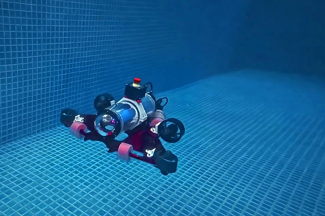
▲ A complete submersible: thruster set, pressure housing and buoyancy material; the controller and battery sit inside the housing
Other mounting orientations
When space does not allow the standard orientation, AHRS_ORIENTATION offers more than thirty alternatives. Find Board Orientation in the ground station under Config/Tuning → Advanced Params, and read the sign of each axis from the table below.
| Value | Meaning |
|---|---|
| Roll90 | Board stands 90° to the right; the arrow still points at the nose |
| Pitch90 | Board tips 90° nose-up; the arrow points straight up |
| Yaw90 | Board turns 90° clockwise; the arrow points to starboard |
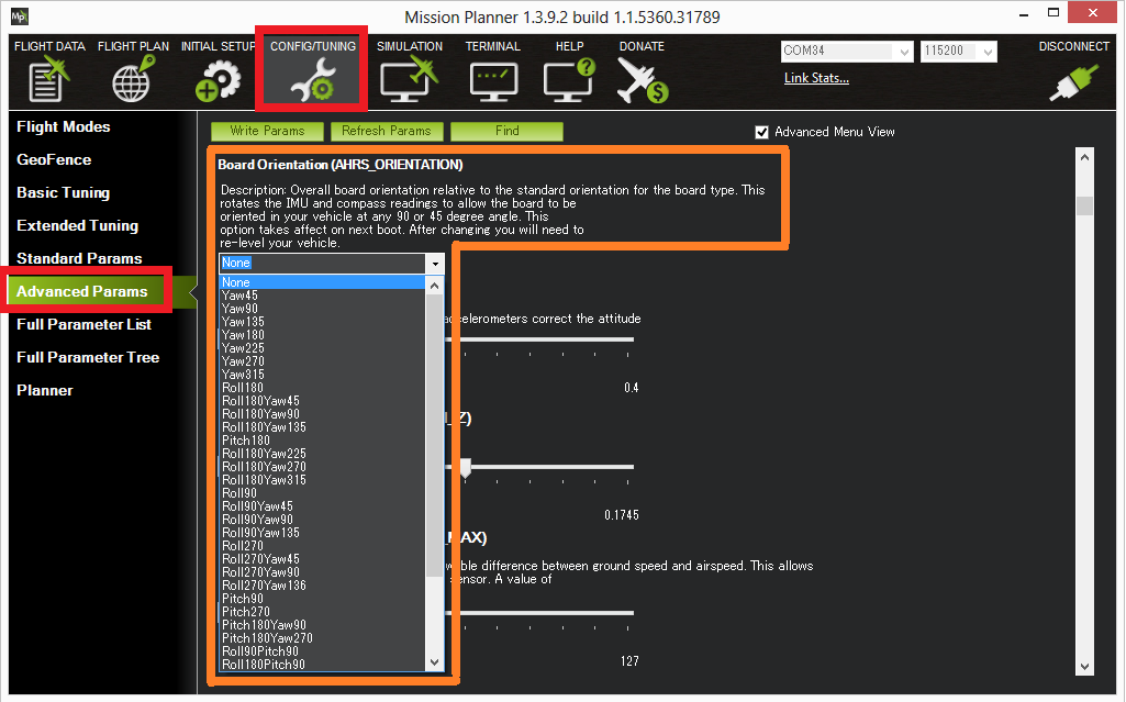
▲ Choose Board Orientation under Advanced Params in the ground station
Set the orientation before calibrating
When the arrow does not point at the nose, set AHRS_ORIENTATION first and calibrate the accelerometer afterwards. Reversing the order gives a wrong attitude calibration, which shows up underwater as tracking sideways when you command forward.
Thrusters, gimbal and gripper
Thrusters occupy the outputs starting at Output 1 according to the frame; the mapping between numbers and function values is in Thruster and ESC connections.
With a gimbal fitted, pan and tilt each take an output, at function 6 (Mount1Yaw) and 7 (Mount1Pitch); a gripper uses 28 (Gripper). All three only move once armed, so confirm the parameter points at the right output before wiring — leaving it at 0 means the output stays silent.
On a tethered vehicle the umbilical runs through a bulkhead connector. Cable length and gauge set the voltage drop, and power and communication travel on separate pairs so ESC noise does not creep into the video feed.