

Hobbywing CAN Power Set
A Hobbywing CAN power set combines the motor and ESC into one unit and speaks DroneCAN: throttle and telemetry share the same three-wire cable, the controller tells the ESCs apart by node ID, and parameters are changed online.
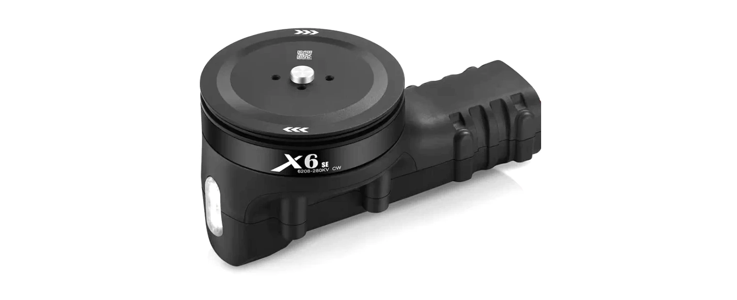
▲ X6 power set
WARNING
You must buy the CAN version. Most models support CAN and PWM redundancy: the PWM and CAN interfaces can be connected at the same time as redundant motor control paths, and the ESC falls back to PWM when CAN communication fails.
NOTE
Power sets ship needing a baud rate and ID configuration before they work.
Hardware connection
Daisy chain: whole-airframe wiring
The ESCs chain in order on CAN1, with a 120 Ω terminator in the far end.
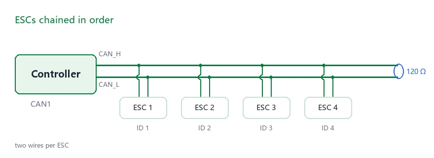
▲ Daisy-chain wiring
Distribution board: one port per ESC
Each ESC gets its own port. Inside, the board is simply a parallel connection, electrically the same as a daisy chain. Unplugging one branch during troubleshooting does not affect the others.
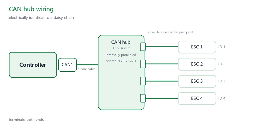
▲ Distribution-board wiring
Wiring for single-unit configuration
During configuration connect only one set: the thick red and black wires to power, the three thin wires CAN_H / CAN_L / GND to CAN1 on the controller.
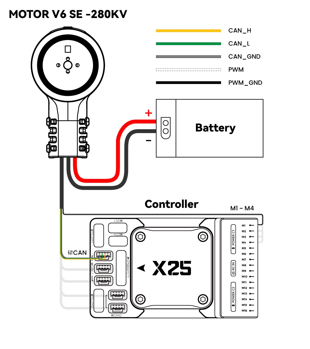
▲ Single-set wiring
Configuration steps
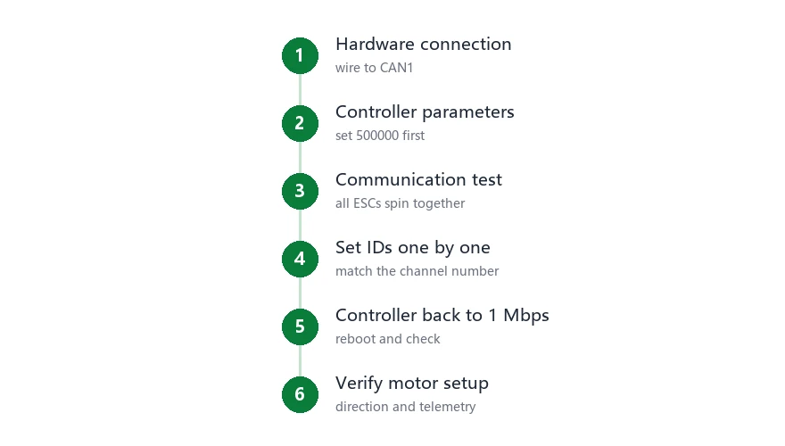
▲ Configuration order
1. Change the controller parameters
Connect the controller to the computer with a USB cable, open Mission Planner and connect. Go to Config / Tuning → Full Parameter List, change the values below, then click Write Params to save.
Set CAN_P1_BITRATE to 500000 first. After every ESC ID has been changed, set it back to 1000000.
| Parameter | Value | Purpose |
|---|---|---|
CAN_P1_DRIVER | 1 | Assigns driver 1 to the CAN1 port |
CAN_D1_PROTOCOL | 1 | DroneCAN protocol |
CAN_P1_BITRATE | 500000 | Link rate; match the factory value first |
CAN_D1_UC_ESC_BM | 15 | Which outputs go over CAN; 1~4 on a quad |
CAN_D1_UC_OPTION | 128 | Enables the Hobbywing command set |
MOT_PWM_MIN / MOT_PWM_MAX | 1000 / 2000 | Aligns with the ESC input range |
SERVOx_FUNCTION | 33 ~ 36 | Filled automatically when the frame type is selected; no assignment means no throttle is sent |
Assigning CAN channels
CAN_D1_UC_ESC_BM is a bitmask where bit n corresponds to output n; tick it and that output goes out over CAN.
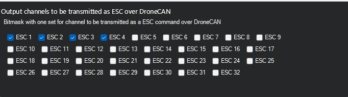
▲ Channel bitmask
| Airframe | Channels on CAN | Value |
|---|---|---|
| Quad | 1 ~ 4 | 15 |
| Hexa | 1 ~ 6 | 63 |
| Octo | 1 ~ 8 | 255 |
| Only some of the channels | Add the bits | — |
Channel numbers must match M1 ~ M8 on the controller; channel 1 is M1.
2. Change the CAN parameters of the power set
Factory values and target values:
| Item | Factory value | Target value | Where to change |
|---|---|---|---|
| Baud rate (Baudrate) | 500 kbps | 1000000 | Baudrate in the config panel |
| Node ID (NodeID) | 1 | 1 ~ 8, matching the output channel | NodeID in the config panel |
| Throttle ID (ThrottleID) | 1 | 1 ~ 8, matching the output channel | ThrottleID in the config panel |
| Report rate (Msg1Rate / Msg2Rate) | Default | 50 / 10 | Config panel |
The RPM report rate must be higher than the voltage and current rate, otherwise frames are dropped, so set Msg1Rate to 50 and Msg2Rate to 10.
3. Communication test
- Connect the CAN wires of all ESCs to CAN1 (or CAN2) on the controller.
- Confirm
CAN_P1_BITRATE= 500000 and restart the controller. - Power the ESCs; when the beeping stops, self-test has passed. Some Hobbywing ESCs need a PWM signal connected to pass self-test.
- Open Initial Setup → Mandatory Hardware → Motor Test in Mission Planner and click Test All Motors. If every motor turns, CAN communication works.
TIP
This step only checks wiring and power. If nothing turns, look at wire order, CAN_P1_DRIVER and whether the ESCs powered up properly — do not touch the IDs yet.
4. Change the IDs one at a time
Wiring: connect only the power set for motor 1 and leave the CAN signal wires of all other ESCs disconnected, so you cannot change the wrong unit.
- Download and install DroneCAN GUI (version 1.2.25 or later).
- Identify the MAVLink or SLCAN serial port of the controller.
- Open DroneCAN GUI and connect to that port.
- Click the √ button to the right of Set local node ID.
- Go to Panels → Hobbywing ESC Panel (Ctrl+Shift+7).
- Select this ESC in the top table and set Baudrate to 1000000.
- Set both ThrottleID and NodeID to this ESC's number (the servo / PWM output port number on the controller), clicking Set after each.
- Wait a few seconds; the values in the top table refresh automatically.
- Move to the next ESC and repeat the steps above.
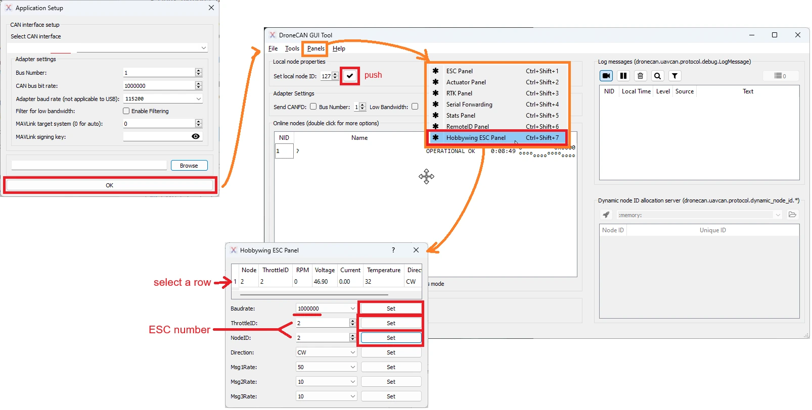
▲ ID change flow
How to choose the ESC number
The ESC number corresponds to the servo output port on the controller:
- With default parameters
SERVO1_FUNCTION= Motor1 andSERVO2_FUNCTION= Motor2, so on a quad the ESC numbers 1~4 are simply 1~4. - If
SERVO2_FUNCTIONhas been set to Motor1, numbering them 1~4 in order is wrong — the number must follow the actual output port. - Example: with PWM signals on Servo9 ~ Servo12, the NodeID and ThrottleID of these four ESCs are 9 ~ 12.
Other settings
| Item | Value | Notes |
|---|---|---|
| Msg1Rate | 50 | Report rate for RPM |
| Msg2Rate | 10 | Report rate for voltage, current and temperature |
| Direction | CW / CCW | Motor direction |
| Throttle_source | CAN / PWM | On some ESCs you can use CAN only, PWM only, or both |
Msg1Rate must be greater than Msg2Rate, otherwise RPM frames are dropped.
Matching IDs to motor positions
| Motor | ThrottleID | NodeID | Controller output |
|---|---|---|---|
| Motor 1 | 1 | 1 | M1 |
| Motor 2 | 2 | 2 | M2 |
| Motor 3 | 3 | 3 | M3 |
| Motor 4 | 4 | 4 | M4 |
| Motor 5 | 5 | 5 | M5 |
| Motor 6 | 6 | 6 | M6 |
| Motor 7 | 7 | 7 | M7 |
| Motor 8 | 8 | 8 | M8 |
WARNING
The numbering must match the physical positions one-to-one. If it is wrong you cannot tell on the bench and the controller raises no alarm, but the mixer is scrambled and the aircraft flips on takeoff.
5. Set the controller back to 1 Mbps
Once every ESC is at 1000000, set CAN_P1_BITRATE back to 1000000, restart, then open the config panel again. All ESCs should be listed this time; a missing one means two IDs collide.
6. Verify the motor setup
Wiring: all ESCs connected to CAN and powered, PWM signals not connected to the controller, ground station connected.
- Check that the ESC information shows up correctly on the status page.
- In the motor test page under optional hardware, check the direction and order of the motors.
- For setups driven by both PWM and CAN: unplug CAN and test PWM alone; then unplug PWM while the motor is spinning and check whether it stops or stutters, to confirm the redundancy works.
Telemetry is read on the status page:
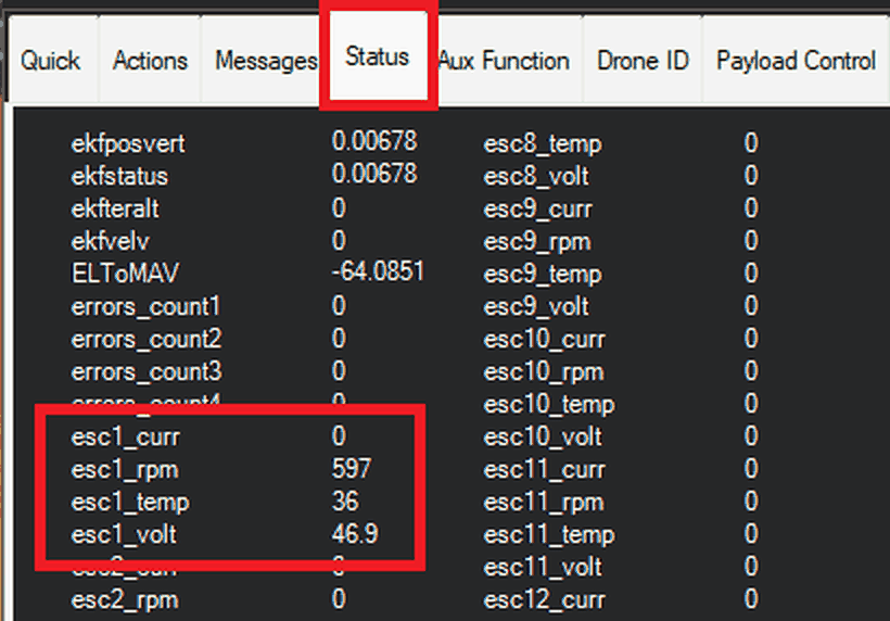
▲ Telemetry data
| Reading | What to check |
|---|---|
esc1_rpm | In hover, motor RPM should be within 10% ~ 15% of each other |
esc1_volt | Should match the battery voltage; a big drop is usually thin wire or a poorly crimped connector |
esc1_curr | At the same throttle, the motors should read close to each other |
esc1_temp | Read it against ambient temperature; a steady climb means checking cooling and prop matching |
These readings are recorded as CESC in the onboard log for review after the flight.
Using ESC voltage as battery voltage
When you do not have a suitable current sensor, you can use the voltage and current reported by the ESCs as battery data.
Wiring: connect the CAN wire of motor 1 to CAN1 on the controller.
| Parameter | Value | Purpose |
|---|---|---|
SERIAL8_PROTOCOL | 22 | SLCAN, a serial-to-CAN adapter |
CAN_P1_DRIVER | 1 | First CAN driver |
CAN_D1_PROTOCOL | 1 | DroneCAN |
CAN_P1_BITRATE | 500000 | ESCs ship at 500k, so match it first; CAN devices at the same baud rate can share one port |
CAN_D1_UC_OPTION | 128 | Tick HobbyWingESC |
BATT_MONITOR | 9 | Battery monitor source set to ESC |
FAQ
- Only one motor turns?
- All ESCs still have ID 1 and none was changed individually
- None of them turn?
- Check the rate first (500k / 1M); check that
CAN_D1_UC_OPTIONis 128; check that CAN_H and CAN_L are not swapped
- The ESC keeps beeping?
- It is not receiving a valid throttle; check
SERVOx_FUNCTIONandCAN_D1_UC_ESC_BM
- They turn but there is no telemetry at all?
CAN_D1_UC_OPTIONdoes not have HobbyWingESC ticked; or the unit is the PWM version
- Direction is reversed?
- Check the direction marking on the motor and swap in a motor that matches the target direction. Or change Direction to CW or CCW in the config panel.
- One ESC is missing after the changes?
- Two IDs collide; power them off one at a time and see which one disappears
- Values revert to factory after a restart?
- Power was cut before the table refreshed after clicking Set; set it again and confirm the value stuck before powering off
Everything on one page
| Parameter | Value | What happens without it |
|---|---|---|
CAN_P1_DRIVER | 1 | No driver on the CAN1 port |
CAN_D1_PROTOCOL | 1 | No DroneCAN on the bus |
CAN_D1_UC_ESC_BM | 15 | Throttle does not go over CAN |
CAN_D1_UC_OPTION | 128 | Motors turn but there is no telemetry |
CAN_P1_BITRATE | 1000000 | Mismatch with the ESCs, nothing responds |
SERVOx_FUNCTION | 33 ~ 36 | Nothing is sent at all |
| ESC Baudrate | 1000000 | Ships at 500k, change one ESC at a time |
| ESC NodeID / ThrottleID | 1 ~ 8 | All ship as 1, change one ESC at a time |