

PX4 Firmware Guide
This chapter describes the points to be aware of when running PX4 firmware on the X25 EVO. The PX4 docs has the complete PX4 guide.
Loading firmware
There are two methods for firmware flashing: online flashing and local flashing. You can choose based on your needs.
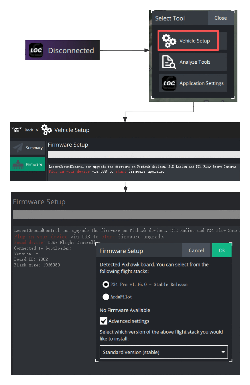
Write firmware online:
- Download and run the LGC Ground Station, then click the LGC icon.
- Navigate to Drone Settings → Firmware, and connect the controller to the computer via USB.
- Select the required "PX4 Pro vxxxx" version and click Confirm.
- After the loading is complete, if no operation is performed, the controller will connect automatically after a dozen seconds.
Local Flashing (Custom Firmware)
- Download the X25 EVO Local Firmware to your local computer.
- Enter the firmware flashing settings, check Advanced Settings, and select the version as Custom Firmware.
- In the pop-up window, select the downloaded local firmware file to complete the flashing.
Serial Mapping
| UART | Device | Port |
|---|---|---|
| USART1 | /dev/ttyS0 | GPS1 |
| USART2 | /dev/ttyS1 | GPS2 |
| USART3 | /dev/ttyS2 | Debug Console |
| UART4 | /dev/ttyS3 | UART4 |
| UART5 | /dev/ttyS4 | TELEM2 |
| USART6 | /dev/ttyS5 | RC |
| UART7 | /dev/ttyS6 | TELEM1 |
Power Module Settings
The X25 EVO comes standard with a PMU2 Lite power module, which supports a 20-70V input and a maximum current of 220A. It can be directly connected to the X25 EVO's Power C1/C2 ports. Once connected, power on the controller without configuring any parameters.
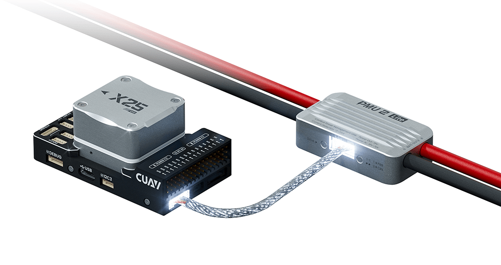
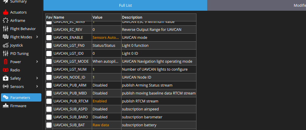
If you modify its settings, you need to set the following parameters and restart the controller after writing.
- Set the
UAVCAN_ENABLEparameter to Sensors Automatic config. - Set the
UAVCAN_SUB_BATparameter to Raw data.
NOTE
Analog power modules are not recommended due to poor accuracy and large temperature drift. It is recommended to use CAN power modules such as PMU2 Lite (with factory calibration and temperature compensation) or CAN smart batteries.
Rated Voltage
The X25 EVO supports triple power redundancy. Pay attention to the voltage range of each interface.
| Power Rail | Type | Voltage Range |
|---|---|---|
| POWER C1 | DroneCAN/UAVCAN Battery Interface | 10V - 18V |
| POWER C2 | DroneCAN/UAVCAN Battery Interface | 10V - 18V |
| USB | USB Input | 4.75V - 5.25V |
TIP
Unlike other controllers, the X25 EVO's POWER C1/C2 ports do not support 5V input, only 10V-18V voltage input. For the default package, the PMU 2lite converts the 20-70V voltage to 15V to power the X25 EVO.
Ethernet Configuration
The X25 EVO supports LAN connection via Ethernet. Devices in the LAN must be on the same IP network (same subnet) to ensure each device has a unique IP address and can communicate with other devices. By default, Ethernet uses DHCP for automatic IP assignment; if DHCP fails, you need to set the IP manually.
Setting the IP Address
- Connect the controller to the computer using a USB cable.
- Open QGroundControl via the MAVLink Console → Analyze Tools.
- Enter the following commands in the MAVLink Console (to write values to the configuration file):
 echo DEVICE=eth0 > /fs/microsd/net.cfg
 echo BOOTPROTO=fallback >> /fs/microsd/net.cfg
 echo IPADDR=10.41.10.2 >> /fs/microsd/net.cfg
 echo NETMASK=255.255.255.0 >>/fs/microsd/net.cfg
 echo ROUTER=10.41.10.254 >>/fs/microsd/net.cfg
echo DNS=10.41.10.254 >>/fs/microsd/net.cfg- After setting the network configuration, disconnect the USB cable and restart the controller.
- After the setup is complete, the configuration information will be saved in the SD card directory
/fs/microsd/net.cfg name=value as follows:
DEVICE=eth0
BOOTPROTO=fallback
IPADDR=10.41.10.2
NETMASK=255.255.255.0
ROUTER=10.41.10.254
DNS=10.41.10.254
Where the values are:
DEVICE: Interface name. Default is .eth0BOOTPROTO: Protocol for getting PX4 IP address. Valid values for proto are: , , (use DHCP but fall back to static address after time, if that fails)dhcp,static,fallbackIPADDR: Static IP address (used if BOOTPROTO is orstaticfallback)NETMASK: Network maskROUTER: The address of the default route.DNS: The address of the DNS server.
Network Connectivity Test
- Open the Windows Command Prompt.
- Enter the command: ping 10.41.10.2
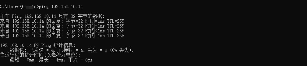
TIP
A response with network latency data indicates that communication is established. A "request timed out" message may mean the IP address is incorrect or communication has failed. For more details, refer to PX4 Ethernet Setup.
Connecting to GCS
Run the LGC Ground Station software. Configure the Ethernet port to transmit MAVLink data.
| Parameter | Value | GCS Display | Description |
|---|---|---|---|
| MAV_2_CONFIG | 1000 | Ethernet | Configure MAVLink to transmit via Ethernet |
| MAV_2_BROADCAST | 1 | Always broadcast | Broadcast messages continuously |
| MAV_2_MODE | 0 | Normal | Send the "normal" set of MAVLink messages (i.e., the GCS set) |
| MAV_2_RADIO_CTL | 0 | Disabled | Disable software restrictions on MAVLink traffic |
| MAV_2_RATE | 100000 | 100000B/s | Maximum transmission rate |
| MAV_2_REMOTE_PRT | 14550 | 14550 | MAVLink remote port 14550 (for GCS) |
| MAV_2_UDP_PRT | 14550 | 14550 | MAVLink remote port 14550 (for GCS) |
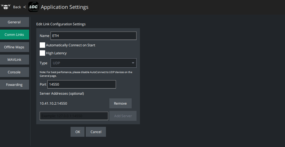
Create a new network connection: Go to Application Settings → Commlinks → Add Connection. Set the connection name, select UDP as the connection type, enter the controller's IP address and port number (14550), then click OK to confirm the creation.
Once created, select the connection to establish communication.
Firmware Compilation
NOTE
Most users do not need to compile firmware; they can directly flash firmware online via LGC/QGroundControl.
Compilation Command
make cuav_x25-evo_defaultDebug Port
The PX4 System Console and SWD run on the FMU Debug port. They can be used with the C-ADB DebugAdapter for debugging configuration.
| Pin | Signal | Volt |
|---|---|---|
| 1 (red) | 5V+ | +5V |
| 2 (blk) | DEBUG TX (OUT) | +3.3V |
| 3 (blk) | DEBUG RX (IN) | +3.3V |
| 4 (blk) | FMU_SWDIO | +3.3V |
| 5 (blk) | FMU_SWCLK | +3.3V |
| 6 (blk) | GND | GND |
Development Guide
- PX4 Source Code Repository
- QGroundControl Ground Station Code Repository
- ArduPilot Development Guide
- Mavlink Protocol
- Droncan Bus Protocol
NOTE
CUAV® does not provide technical support for secondary development of firmware or software. For related questions, please read the relevant guides carefully.