

ArduPilot Firmware User Guide
This chapter describes key points to note when running ArduPilot firmware on the X25 EVO. In addition to this chapter, you may also need to read the following content:
- X25 EVO Quick Wiring
- ArduPilot copter Tutorial
- ArduPilot Plane Tutorial
- ArduPilot VTOL Tutorial
- ArduPilot WIKI
- LGC Ground Station
Loading Firmware
The X25 EVO® controller supports ArduPilot. The following mainly explains how to load the ArduPilot firmware.
TIP
The X25 EVO supports firmware versions 4.6.3 and above.
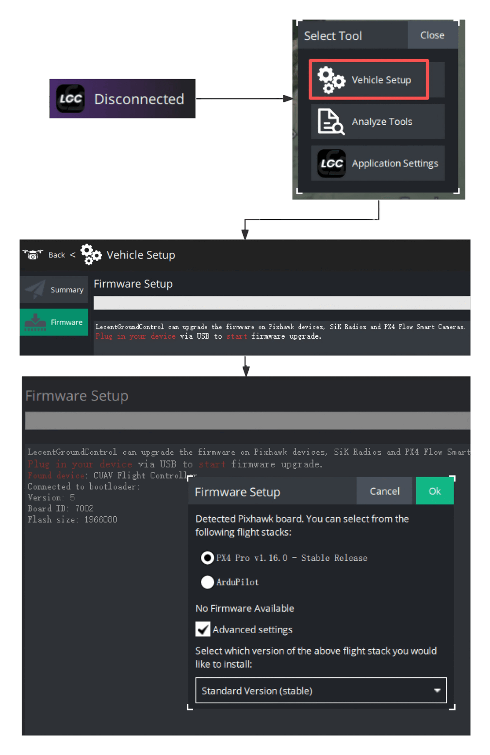
Online Firmware Flashing:
- Run the LGC Ground Station
- Click the LGC icon > Vehicle Settings > Firmware.
- Connect the device to your computer via USB.
- Select the type of firmware to flash.
Load local firmware:
Download the firmware to your local device:
Then follow these steps to flash:
- In the firmware flashing settings, check Advanced Settings.
- Select Custom Firmware as the version.
- In the pop-up window, choose the downloaded firmware file.
GPS/RTK Configuration
TIP
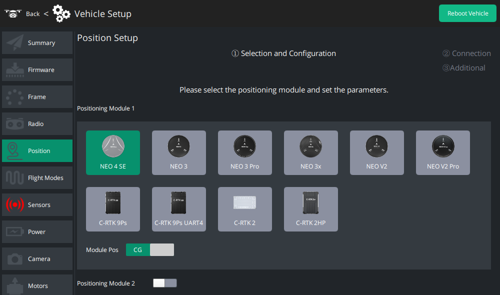
The LGC Ground Station supports graphical configuration of GPS/RTK modules. Click the corresponding GPS/RTK icon and follow the system prompts for automatic configuration. You can configure the GPS position offset via the module position slider, and configure GPS2 via the "Positioning Module 2" slider.
Power Module
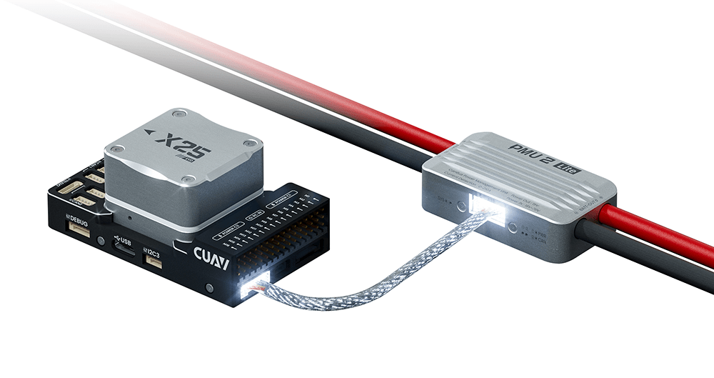
The X25 EVO comes standard with the PMU2 Lite power module, which supports 20–70V input and can measure a maximum current of 220A. It can be directly connected to the Power C1/C2 port of the X25 EVO.
Airspeed Sensor Configuration
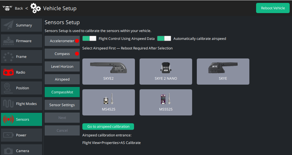
For airframes that require an airspeed sensor, such as Plane/vertical and VTOL, you can configure it in LGC > Vehicle Settings > Sensors > Airspeed Sensor.
TIP
To zero/calibrate the airspeed: Go to Flight View > Real-Time Properties > Airspeed Calibration.
Accelerometer/Gyroscope/Compass Calibration
TIP
Calibrate the accelerometer, gyroscope, and compass on the Sensor Calibration page. Follow the LGC guide to complete the process.
UART Mapping
| SERIAL | Mark |
|---|---|
| SERIAL0 | USB |
| SERIAL1 | UART7 (TELEM1) |
| SERIAL2 | UART5 (TELEM2) |
| SERIAL3 | USART1 (GPS1&SAFETY) |
| SERIAL4 | USART2 (GPS2) |
| SERIAL5 | UART4 |
| SERIAL6 | USART3 (DEBUG/DSU) |
| SERIAL7 | OTG2 (SLCAN) |
NOTE
The TELEM1 and TELEM2 ports support flow control (RTS/CTS); other UARTs do not have RTS/CTS pins. All UARTs are equipped with fully functional DMA.
RC Input
Hardware Connection Diagram
The RC IN port supports all one-way RC protocols (SBUS/PPM/DSM).
DSM/PPM/SBUS Receivers
Use Dupont wires to connect the receiver to the RC IN port—no additional parameter settings are required.
Receivers with Two-Way Protocols (e.g., CRSF/ELRS)
For receivers with two-way telemetry protocols (such as CRSF/ELRS), connect them to a UART port. The following is a setup tutorial (taking SERIAL2 (UART5/TELEM2) for two-way RC as an example):
ELRS Receivers
Connect the receiver to the TELEM2 port and set the following parameters:
- SERIAL2_PROTOCOL=23;
- SERIAL2_OPTIONS=0;
- RSSI_TYPE=3;
- RC_OPTIONS=8192 (Use 420kbaud for ELRS protocol);
- Save the parameters and restart the controller.
CRSF Receivers
- SERIAL2_PROTOCOL=23;
- SERIAL2_OPTIONS=0;
- RSSI_TYPE=3;
FPort Receivers
- SERIAL2_PROTOCOL=23;
- SERIAL2_OPTIONS=7;
- RSSI_TYPE=3;
TIP
Any UART can be used to connect an RC receiver in ArduPilot, and it is compatible with all protocols except PPM. For details, refer to Radio Control Systems.
PWM Output
The X25 EVO supports 16 PWM output channels, which are divided into 5 groups. Each group uses a different timer—only one output rate or protocol can be used for all channels in the same group.
PWM Output Grouping:
- PWM 1–4: Group 1 (TIM5)
- PWM 5–8: Group 2 (TIM4)
- PWM 9–11: Group 3 (TIM1)
- PWM 12–14: Group 4 (TIM8)
- PWM 15–16: Group 5 (TIM12)
NOTE
Channels in the same group must use the same output rate. If any channel in a group uses DShot, all channels in that group must use DShot. Channels 15 and 16 only support PWM—they do not support voltage levels or DShot.
TIP
All channels support switching between 3.3V/5V PWM. For long cable runs or high-power systems, 5V PWM is recommended. Use the BRD_PWM_VOLT_SEL parameter to set the PWM voltage level.
GPIO
All servo outputs can be used as GPIOs (for relays, camera shutters, RPM, etc.). To use a servo output as a GPIO, set SERVOx_FUNCTION=-1 (where x is the pin number).
GPIO Pin Mapping:
| Pin name | SERVO SN | GPIO number |
|---|---|---|
| M1 | SERVO1 | 50 |
| M2 | SERVO2 | 51 |
| M3 | SERVO3 | 52 |
| M4 | SERVO4 | 53 |
| M5 | SERVO5 | 54 |
| M6 | SERVO6 | 55 |
| M7 | SERVO7 | 56 |
| M8 | SERVO8 | 57 |
| M9 | SERVO9 | 58 |
| M10 | SERVO10 | 59 |
| M11 | SERVO11 | 60 |
| M12 | SERVO12 | 61 |
| M13 | SERVO13 | 62 |
| M14 | SERVO14 | 63 |
| M15 | SERVO15 | 64 |
| M16 | SERVO16 | 65 |
Example: To use M14 as a relay, set Relay_pin=63.
Analog Input
The X25 EVO has three analog input ports: ADC Pin13 → ADC 3.3V ADC Pin12 → ADC 6.6V ADC Pin10 → RSSI
RSSI
The X25 EVO has an RSSI (voltage signal) telemetry strength monitoring port. Enable it by setting the following parameters:
- 'RSSI_TYPE' = 1
- 'RSSI_ANA_PIN' = 10
Compass/Magnetometer
The X25 EVO has a built-in RM3100 compass. However, due to potential interference, this board is usually used with an external I2C compass (as part of a GPS/compass combination). Priority should be given to using the external compass (e.g., the compass on a GPS) as the primary compass.
Ethernet Port Configuration
The X25 EVO has an ETH port. Configure it by following the ArduPilot Ethernet Configuration Tutorial.
Development Guide
- ArduPilot Source Code Repository
- Mission Planner Source Code Repository
- ArduPilot Development Guide
- Mavlink Protocol
- DroneCAN Bus Protocol
IMPORTANT
CUAV® does not provide technical guidance for secondary development of firmware or software. For related questions, please carefully read the relevant guides or seek assistance from the ArduPilot discordchannel.