

Motor and Servo Connections
Rover firmware points steering and throttle at specific outputs through SERVOx_FUNCTION. Wiring falls into two cases depending on the chassis: steering and throttle on separate channels, or one motor channel per side. Pick the section that matches your chassis, finish the wiring and the parameters together, then power up.
Steering and throttle on separate channels
Most RC cars work like a real car: steering and throttle are two separate mechanisms. The steering servo drives the front wheels and connects to Output 1 (SERVO1); the drive ESC sets rear wheel speed and connects to Output 3 (SERVO3).
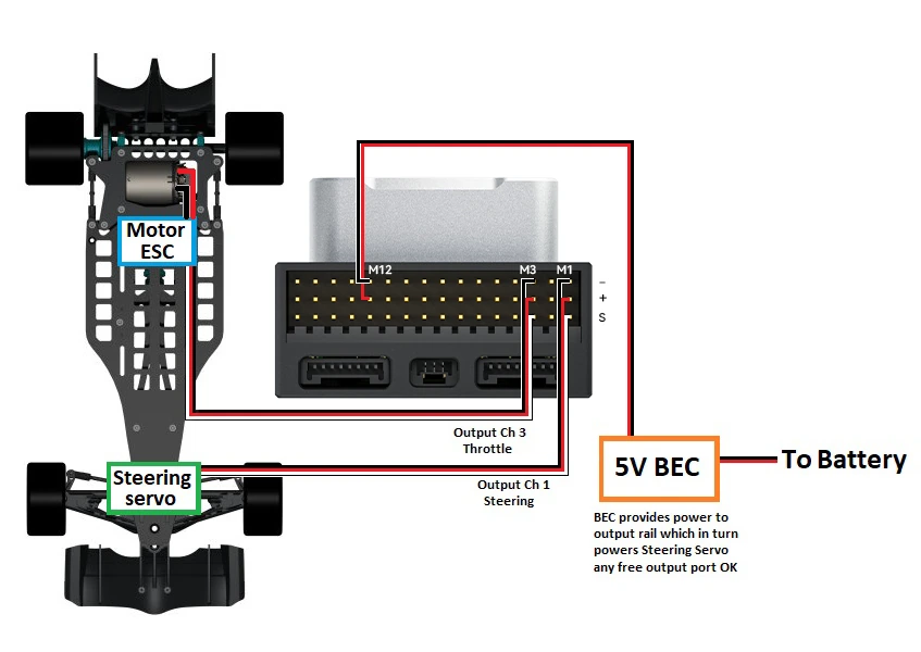
▲ Servo on Output 1, ESC on Output 3; the 5 V BEC feeds the output rail and the servo draws its power from there
| Parameter | Value | Notes |
|---|---|---|
SERVO1_FUNCTION | 26 | Ground Steering |
SERVO3_FUNCTION | 70 | Throttle |
Both are already the factory default, so they only need setting if you changed channels. If the steering does not reach full lock, adjust SERVO1_MIN / SERVO1_MAX; if centre is off, adjust SERVO1_TRIM; if a right input steers left, set SERVO1_REVERSED to 1.
With more than one drive motor, each ESC takes an output of its own and all of them are set to 70: a second ESC on Output 2 means SERVO2_FUNCTION = 70, and so on. The x in SERVOx is simply the output the ESC is plugged into.
Skid steering
A skid-steer chassis has no steering mechanism; it turns by running the two sides at different speeds. The left drive goes to Output 1 and the right drive to Output 3.
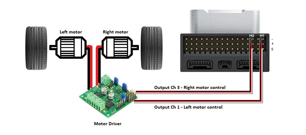
▲ Left and right motors each reach Output 1 and Output 3 through one channel of the driver board
| Parameter | Value | Notes |
|---|---|---|
FRAME_CLASS | 1 | Ground vehicle; 2 is boat, 3 is balance bot |
SERVO1_FUNCTION | 73 | ThrottleLeft |
SERVO3_FUNCTION | 74 | ThrottleRight |
Left and right cannot be swapped
With 73 and 74 swapped, driving straight looks fine but steering is inverted: command a left turn and the vehicle turns right. Swap the channels in that case; do not paper over a wiring mistake with SERVOx_REVERSED.
Omnidirectional chassis
An omnidirectional chassis uses omni or Mecanum wheels to move sideways without changing heading. ArduPilot supports the X, Plus and 3 layouts, and which output each motor uses is fixed by its number.
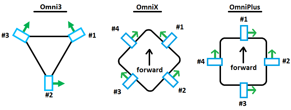
▲ Top view, arrow towards the front; the numbers are the order in which motors connect to MAIN1~MAIN4
Mecanum wheels are a different kind of omni wheel with rollers set at an angle, and they number the motors differently.
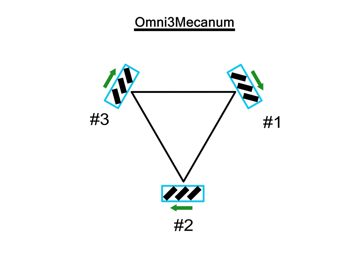
▲ Three-motor Mecanum layout; roller orientation decides the numbering
| Parameter | Value | Notes |
|---|---|---|
FRAME_TYPE | 1 / 2 / 3 / 4 | Omni3 / OmniX / OmniPlus / Omni3Mecanum |
SERVO1_FUNCTION ~ SERVO4_FUNCTION | 33 ~ 36 | motor1 ~ motor4, wired in the order shown above |
Wheel encoders
The controller accepts up to two AB-phase encoders, one per side of the vehicle, with the A and B phases each taking an output. Wiring order, wire colours and parameter settings are in Wheel encoder setup.
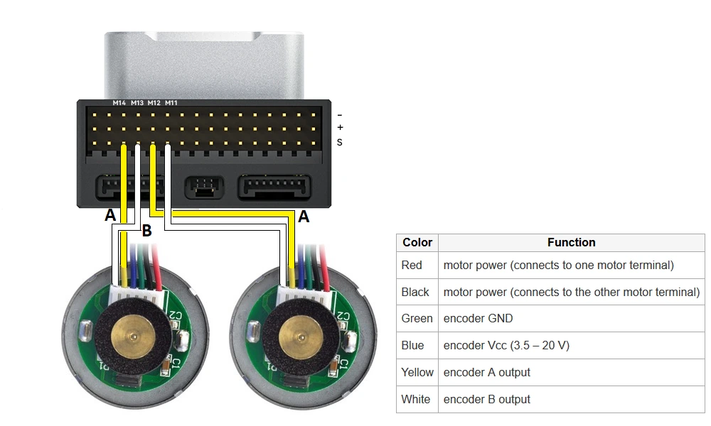
▲ A and B each take an output; yellow is phase A and white is phase B, while red and black carry motor power