

T-Motor DroneCAN Power Set
T-Motor ESCs that support DroneCAN talk over a CAN bus, driving the motors and reporting RPM, voltage, current and temperature at the same time. Details differ between models, so check the vendor manual; the steps below are the general wiring and configuration flow.
Hardware connection
Wiring for a single power set: the thick red and black wires go to the battery; the three thin wires CAN_H / CAN_L / CAN_GND go to CAN1 on the controller.
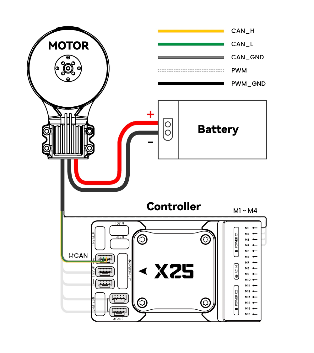
▲ Single-set wiring
Multiple power sets chain in order on the same CAN1, with a 120 Ω terminator in the far end.
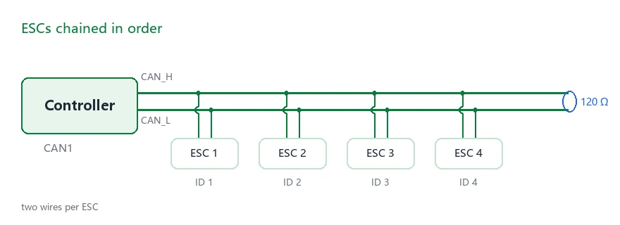
▲ Daisy-chain wiring
NOTE
Confirm the model you bought is the CAN / DroneCAN version. On some models CAN and PWM are two separate versions.
Controller parameters
| Parameter | Value | Notes |
|---|---|---|
CAN_P1_DRIVER | 1 | Assigns driver 1 to the CAN1 port |
CAN_D1_PROTOCOL | 1 | DroneCAN protocol |
CAN_P1_BITRATE | 1000000 | Matches the 1 Mbps default of these ESCs |
CAN_D1_UC_ESC_BM | 15 | Channels 1~4 for a quad; 63 for a hexa, 255 for an octo |
CAN_D1_UC_ESC_OF | 0 | Offset when the ESCs sit on channels 5~8, saves bandwidth |
CAN_D1_UC_ESC_RV | 0 | Bitmask of reversible ESCs; keep 0 on a normal multirotor |
MOT_PWM_MIN / MOT_PWM_MAX | 1000 / 2000 | Matches the output range to the ESC input range |
SERVOx_FUNCTION | 33 ~ 36 | Motors 1~4 map to 33~36; no assignment means no CAN command is sent |
BRD_SAFETY_DEFLT | 0 | Disables the safety switch during debugging so throttle is not blocked while disarmed |
WARNING
Restart the controller after changing CAN parameters. An unassigned SERVOx_FUNCTION is the most common cause of "the motor does not move at all".
Assigning CAN channels
CAN_D1_UC_ESC_BM is a bitmask where bit n corresponds to output n; tick it and that output goes out over CAN.
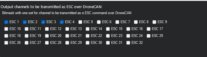
▲ Channel bitmask
| Airframe | Channels on CAN | Value |
|---|---|---|
| Quad | 1 ~ 4 | 15 |
| Hexa | 1 ~ 6 | 63 |
| Octo | 1 ~ 8 | 255 |
| Only some of the channels | Add the bits | — |
Channel numbers must match M1 ~ M8 on the controller; channel 1 is M1.
Setting the ESC ID
Every ESC needs a unique ID on the bus, mapped one-to-one to its motor channel (motor 1 → ID 1, motor 2 → ID 2, and so on).
The animation below shows the whole process: connect, select the ESC node, click Menu to open the parameter window, change ESC_NODE_ID to the target number, then click Write Params to save.
▲ Changing the ESC ID
WARNING
Remove the propellers before changing IDs or direction, or before updating firmware.
Verifying the motor setup
Wiring: all ESCs connected to CAN and powered, PWM signals not connected to the controller, ground station connected.
- Check that the ESC information shows up correctly on the status page.
- In the motor test page under optional hardware, check the direction and order of the motors.
- For setups driven by both PWM and CAN: unplug CAN and test PWM alone; then unplug PWM while the motor is spinning and check whether it stops or stutters, to confirm the redundancy works.
Telemetry is read on the status page:
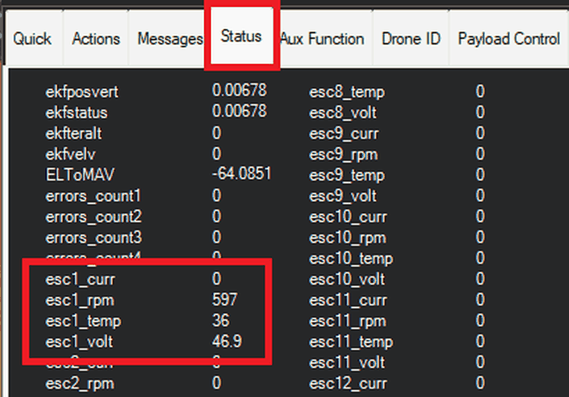
▲ Telemetry data
| Reading | What to check |
|---|---|
esc1_rpm | In hover, motor RPM should be within 10% ~ 15% of each other |
esc1_volt | Should match the battery voltage; a big drop is usually thin wire or a poorly crimped connector |
esc1_curr | At the same throttle, the motors should read close to each other |
esc1_temp | Read it against ambient temperature; a steady climb means checking cooling and prop matching |
Firmware update
- Firmware for these ESCs usually updates only through the vendor's tool; third-party tools cannot flash them.
- Several ESCs can be updated over the same CAN bus, but only one node updates per power cycle, so power-cycle repeatedly as prompted.
- After the update, power-cycle again and confirm the version number is correct.
Debugging notes
- Some models do not report status on power-up; they only start sending data periodically after receiving a CAN throttle command. Seeing no telemetry before the motor test is normal.
- No throttle is output until the safety switch is released. During debugging you can temporarily set
BRD_SAFETY_DEFLTto 0, or press the safety switch until it stays lit. - Use motor test to confirm the direction of each motor; when the direction needs changing, do it in the vendor's tool.
Telemetry and logs
- Live data: the ground station status page shows RPM, voltage, current and temperature for every ESC.
- Onboard log: recorded as
CESCmessages, covering RPM, voltage, current, temperature, power percentage and error count for post-flight analysis.